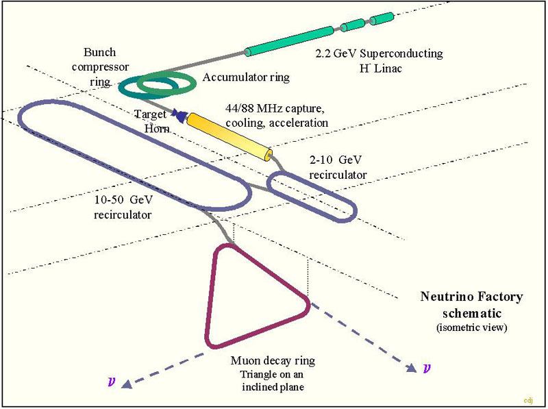
Figure 2.1 Schematic of Neutrino Factory showing a triangular decay
ring
[Author list] The European Neutrino Factory Study
1 Introduction
The production of neutrinos from the decay of muons circulating in a storage ring (neutrino factory) has of late attracted considerable attention. The original interest started with the study of muon colliders [1,2]. These colliders could open the way to lepton collisions at extremely high energies. Circular electron colliders are limited in energy due to the high synchrotron radiation emitted by the electrons. Although this radiation decreases with larger radius of the accelerator, it increases with the fourth power of the energy. For this reason it seems unrealistic to build circular machines with higher energies than LEP. The only possibility for higher energies seemed to be linear colliders with all their technical challenges. Another solution is the use of heavier leptons in circular colliders, as the limiting synchrotron radiation power at the same energy is inversely proportional to the fourth power of their rest mass. Muon beams seem to be possible candidates for this purpose. Muons can be produced by the decay of pions, which in turn can easily be produced by bombarding a target with high-energy protons. The most serious problem is the production of muon beams with the high phase-space density necessary for collider operation. In spite of some impressive progress towards this goal, no technically feasible solution has yet been found. A substantial R&D effort will be required to make progress.
With the recent confirmation of neutrino oscillations, the situation has changed drastically. High-energy muons, stored in a decay ring with long straight sections pointing towards distant detectors, provide a unique beam of high-energy electron neutrinos. This allows precise determination of several parameters of the neutrino mass matrix, possibly including the CP violating phase, which would otherwise be inaccessible. The reduced requirements (compared to a muon collider) of this neutrino factory have brought much closer to reality the concept of high intensity muon machines. The R&D effort for the muon colliders turns out to be very useful for a neutrino factory, and the increased interest from the physics side has produced a spate of activity on the accelerator side, so that considerable progress has been made towards a neutrino factory design [3,4,5]. It is interesting to note that, in turn, a part of this progress is also beneficial for the design of a muon collider.
The interest demonstrated by the neutrino physics community resulted in the year 1999 in the first joined (Accelerator physicists and neutrino physicists) workshop in Lyon (NuFact'99) with a large attendance by American, Asian and European physicists. It was only logical to continue with this successful experiment in the year 2000 (NuFact'00 in Monterey). The American Muon Collider Collaboration changed its name to Neutrino Factory and Muon Collider Collaboration and a lot of activities started in Europe and Japan. NuFact'01 was held in Tsukuba.
In late 1999 a feasibility study for a Neutrino Factory was started at FNAL and presented its results in spring 2000. This study demonstrated clearly the feasibility of such a machine and made detailed recommendation for a R&D program. Another study ("Study 2") has been completed at BNL with the aim of improving the neutrino yield and including some site specific issues,
At CERN activities had started in 1999 and produced a workplan in 2000. CERN's plans foresee to make use of the SPL (Superconducting Proton Linac) as the first stage of the "proton driver". This machine, if built, has many advantages and potentially other uses in addition to the neutrino factory. It provides more "safety margin" for the LHC beam quality, it can boost considerably the intensity for the radioactive beams at the ISOLDE facility, it can provide a "classical" superbeam for neutrino experiments and it could provide stopped muons. It has characteristics similar to the planned machines for spallation neutron generation, energy amplifiers, radioactive waste transmutation and radioactive isotope production for medical applications. The future of muon colliders depends also very much on the availability of such high power machines.
CERN is proposing a reference scenario, which serves as guide line for its activities towards a neutrino factory. With the help of other laboratories, CERN has initiated a study on some of the many technological challenges of such a facility. Discussions about the exact scope of the different collaborations are under way.
2 The basic concept of the CERN neutrino factory scenario
The reference scenario described here is based on the particular situation at CERN. It is intended as a working hypothesis that is in part CERN specific, while being dominated by the wish to achieve the required high muon fluence [6].
The requirements, as expressed in the NuFact'99 workshop at Lyon [7], set a target fluence of 1021 muons per year injected into the storage ring. The present CERN accelerators are not suited to easy upgrade of the available beam power. However, a proposal [8,9] has been made to replace the CERN PS injector complex (50 MeV linac and 1.4 GeV booster) by a linear accelerator, destined primarily as injector into the PS for the LHC beam. It was intended to offer a higher brilliance LHC beam from the PS. The basic idea in proposing to build this linac is to re-use the cavities, klystrons and auxiliary equipment from LEP after this machine has been shut down. Average beam power of 4 MW appears to be feasible. We envisage in our scenario to use this linac with a beam energy of only 2.2 GeV, which is relatively low. The results of the HARP experiment [10], which will measure pion production in this energy range and will produce data during 2001 and 2002. These results will be crucial in the final assessment of our choice of the proton driver.
The neutrinos coming from a neutrino factory will be produced by muon decay. Protons hitting a target will produce pions, which decay very rapidly into muons. The pions produced by hitting a target with an (even well defined) proton beam will not form a beam in the normal meaning of the word, but will depart from the target into all directions and with a very large energy spread. The subsequent decay of the pions into muons does not improve this situation. Using only those muons which are contained in a small angle and with a very limited energy spread would result in throwing away most of the produced muons and result in an extremely low intensity.
Hence it is necessary to collect more of the produced muons and to reduce their energy spread and to modify the angular distribution as to fit into a smaller aperture. Only in this way can one produce a beam which can be accelerated and stored in a technically reasonable machine.
The first process is called "phase rotation" and is basically the acceleration of low energetic muons and the deceleration of high energy muons. This can be achieved by conventional rf cavities if the muons are separated in space and hence their acceleration or deceleration will depend on the rf phase.
The second process is called "cooling", which is achieved by slowing down the muons and accelerating them in the forward direction with rf cavities. Ideally one would stop the muons completely and accelerate them, which would result in the best beam.
However, the muon lifetime is only 2.4 ms and most of the muons would decay before being accelerated. For the very same reason fast acceleration using high gradients is necessary to profit from the relativistic increase of their lifetime in the laboratory frame.
To allow for phase rotation the neutrino factory requires the production of beam pulses consisting of relatively short trains of very short proton bunches (nanoseconds). This allows the use of bunch rotation to reduce the large energy spread within the muon bunches. The pulse repetition rate must not be too high; otherwise the energy consumption of the subsequent machines becomes too high. Also it would be wasteful if a new injection into the storage ring took place before the previous batch had decayed (the ring design employs full-aperture kickers and so injection would kill the previous circulating muon beam). The linac cannot directly provide a suitable beam; hence it will operate with H- ions and inject into an accumulator ring, using charge exchange injection to achieve a large circulating proton current. Bunches will be formed in this ring with suitable rf cavities. They will be transferred into a compressor ring for further shortening of their length. The linac will operate at 50 Hz and initial pulse duration of 2.8 ms at a mean current of 13 mA during the pulse. After accumulation and compression the resulting beam pulse, now shortened to 3.3 ms - the revolution period in the accumulator and compressor rings - contain a bunch train comprising 140 bunches spaced at 44 MHz frequency. The repetition rate is 50 Hz. It is assumed that the accumulator and compressor rings will be accommodated in the old ISR tunnel.
This beam will irradiate the production target. In our case at 4 MW and 2.2 GeV, to ensure adequate cooling we must use a moving target. Some work has begun at RAL on the development of a moving toroidal target made out of solid material; an alternative possibility is a liquid (metal) target. Some liquid metal experience is available at CERN and experiments are under way (together with BNL) to exploit the feasibility of this approach.
It is necessary to capture the pions produced in the target. At CERN there is considerable experience with magnetic horns, for the collection of antiprotons and in the production of (conventional) neutrino beams. It is therefore worthwhile to investigate the possibility of using a magnetic horn also for the neutrino factory.
Because of the high repetition rate and the large number of bunches, an rf system is proposed for the manipulation of the muons after the pion decay. The rf system will capture and phase-rotate the muon bunches, and it will also be used in the ionization cooling of the muonbeam in order to compensate the loss of energy of the muon due to ionization when passing through matter. Further acceleration of the muons to 2 GeV is performed in a special linac with solenoid focusing up to around 2 GeV, followed by more conventional quadrupole focusing. Subsequent acceleration takes place in two Recirculating Linacs (RLA) to an energy of 50 GeV. The muons are then injected into a storage ring (decay ring) where they are kept for the duration of the useful beam lifetime (1.2 ms at this energy). The muons decaying in the long straight sections of this ring produce the required neutrino beams. A schematic layout of this CERN reference scenario is presented in Figure 2.1.
Figure 2.1 Schematic of Neutrino Factory showing a triangular decay
ring
Figure 2.2 shows a possible layout of the neutrino factory on the CERN site. Please note that the muon starage ring (MSR) needs to be properly aligned once the detector sites are fixed. Figure 2.3 shows the tunnel elevations for a typical machine complex.
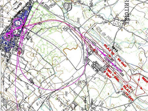
Figure 2.2 Possible layout of a Neutrino Factory on CERN site
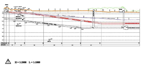
Figure 2.3 Tunnel elevations of a Neutrino Factory on CERN site
3.1 Generalities
The proton beam power of 4 MW can be provided by various types of accelerator set-ups, which differ in terms of beam energy and/or time structure. To limit the power consumption of the whole complex, which is approximately proportional to the repetition rate, slow cycling is preferred, with a maximum value of approximately 50 Hz. Four typical proposals characterising the possible choices are summarised in Table 3.1.
Rapid Cycling Synchrotrons (RCS) are favoured for kinetic energies above 2.5 GeV. The repetition rate is inversely proportional to the energy (from 50 Hz at 5 GeV [11], to 15 Hz at 16 GeV [12] and 8 Hz at 30 GeV [13]). An attractive feature is the possibility to have a large distance between bunches.
For energies below 2.5 GeV, a Linac complemented with storage rings is sufficient. The cycling rate can be made large, and the required value of ~ 50 Hz is the minimum achievable at 2.2 GeV. The distance between bunches has to be small in this scheme, to limit the energy spread of the shortened bunches at ejection.
Table 3.1: Comparison between proton drivers
|
|
|
|
|
|
| Linac & storage rings [14] |
|
|
|
|
| 5 GeV RCS [11] |
|
|
|
|
| 15 GeV RCS [12] |
|
|
|
|
| 30 GeV RCS [13] |
|
|
|
|
The Linac solution is presently preferred at CERN, because of its flexibility as a potential injector of the CERN PS, because of the economical advantage of re-using most of the LEP rf hardware, and because of its capability to be extended to higher beam powers. This low-energy scenario combines a 2.2 GeV, 50 Hz Superconducting H- Linac (SPL) with an accumulator and a compressor ring: PDAC - the Proton Driver Accumulator - Compressor. This would fit well into the ISR tunnel of circumference 948 m. A 44 MHz rf system matching the muon rotation and cooling system is a natural choice, alleviating at the same time the bunch compression task. This choice, which is referred to as the reference scenario, will be reviewed at the end of 2001, using the results from the HARP experiment [10], which will measure the production of p+ and p- from different proton beam energies and different types of targets.
Meanwhile, in order to cope with possible evolution in the neutrino factory design, the use of rapid cycling synchrotrons for the 4 MW proton drivers has also been studied. In collaboration with RAL two site-independent 5 GeV, 50 Hz and 15 GeV, 25 Hz drivers have been investigated. In the case that slow repetition rates are finally preferred, we opted to study a 30 GeV, 8 Hz synchrotron (upgradable to 8 MW, 15 Hz by adding a second ring), again using the ISR tunnel for the driver. RAL also designed a 180 MeV, 56 mA linac, derived from the ESS study [15], which would be the injector in all three synchrotron scenarios.
The low repetition rate has a number of advantages. The average power dissipated in the magnetic horn is substantially reduced, the horn lifetime is increaded and the design of its power supply is much simplified; the reduction of the pulsing rate of the large superconducting rf system in the Recirculating Linear Accelerator (RLA) is very welcome as it reduces the power consumption considerably.
3.2 The Superconducting Proton Linac
An 800 m long Superconducting Proton Linac (SPL) is proposed [14], which makes extensive use of the large inventory of rf equipment dismantled from LEP to accelerate H- ions up to 2.2 GeV kinetic (Figure 3.1). Room temperature rf structures are used up to 120 MeV, and Superconducting resonators from 120 to 2200 MeV. The main parameters of the SPL are listed in Table 3.2.
Table 3.2 : SPL main parameters
| Ions | H- |
| Kinetic energy | 2.2 GeV |
| Mean beam power | 4 MW |
| Repetition rate | 50 Hz |
| Beam pulse duration | 2.2 ms |
| Mean current during the pulse | 11 mA |
| Number of ions per pulse | 1.5´1014 |
| Number of ions per second | 1.1´1016 |
| rf and bunch frequency | 352.2 MHz |
| Overall length | 799 m |
| Peak rf | 32 MW |
| Mean power consumption | 38 MW |
| Transverse normalised rms emittance | < 0.6 mm |
| Bunch length at the entrance of the accumulator (total) | 0.5 ns |
| Energy spread at the entrance of the accumulator (total) | 0.4 MeV |
| Energy jitter at the entrance of the accumulator (max.) | +/- 2 MeV |
Supplied by an H- ion source at 45 keV potential, the beam is bunched and accelerated to 3 MeV in an rf quadrupole (RFQ) operating at 352 MHz. At this energy, a fast chopper eliminates the unwanted bunches and provides the proper time structure for an optimum longitudinal capture in the accumulator synchrotron after the Linac (see section 3.2). A second RFQ brings the energy up to 7 MeV. Between 7 and 18 MeV, conventional Drift Tube Linac (DTL) structures are used, with quadrupolar magnets housed in the drift tubes, inside the rf resonators. Above 18 MeV and up to 120 MeV Coupled Cavity Drift Tube Linac (CCDTL) structures are employed, with quadrupoles outside the resonators. Between 120 and 390 MeV, new modules containing multi-cell superconducting cavity modules are needed. From 390 MeV to 1.1 GeV, 48 new b=0.8 five cells cavities are fitted inside 12 LEP cryostats. Above 1.1 GeV, 29 LEP modules (116 cavities) are used without modification (see Fig. 3.1).
Figure 3.1 SPL block diagram
A total of 44 LEP klystrons are employed for rf power generation (as many klystrons as in LEP-2), as well as 41 LEP 4 cavities modules (out of the 68 formerly used in LEP-2), among which 12 are refurbished with new cavities.
Radiation handling is a key concern at such a high beam power. In order to permit hands-on maintenance, losses must be kept below 1W/m, a challenging figure that requires an adequate machine design with a careful control of beam halo as well as an effective collimation systems. The large aperture of the LEP-2 cavities is an interesting advantage in this respect because most of the halo particles that develop after the initial collimation are transported to the end of the linac and dumped in collimator dumps where radiation issues are localised and properly addressed.
Although a significant fraction of the total hardware is already available, R&D is needed for all equipment of the 120 MeV room temperature linac as well as for the low-beta superconducting cavities (all cavities below 1 GeV). The machine layout will be refined using the results of these hardware developments and the outcome of extended beam dynamics studies including the analysis and minimisation of halo.
Conventional but important design and construction work is also going
to be needed for the focusing, diagnostic and control equipment, the cryoplants,
and the civil engineering of the 800 m accelerator tunnel and technical
gallery.
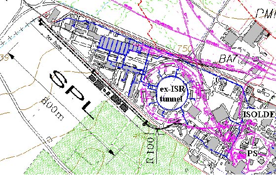
Figure 3.2 Proton driver complex on the CERN site |
3.3 Accumulator and compressor rings
The detailed characteristic
features of the four proton drivers are summarised in Table 3.3, which
also outlines the methods of bunch compression typical for the scenarios
and their specific problems. In the reference scenario,
the SPL is located as shown in Figure 3.2, and the accumulator and compressor
rings are situated inside the ex-ISR tunnel. The 2.2 GeV H-
ions from the linac pass through a stripping foil at the entrance of the
accumulator ring where they lose both electrons. The resulting protons
are efficiently accumulated over 660 turns in small emittance bunches circulating
in the accumulator ring. 140 of the 146 buckets generated by the 44 MHz
rf system are progressively populated by up to 1.08´1012
p/b. At the end of accumulation, the bunches are fast ejected and transferred
into the compressor ring, where bunch compression takes place in 7 turns,
with 2 MV at 44 MHz and 350 kV at 88 MHz. The 1 ns rms bunches are then
ejected onto the pion production target.
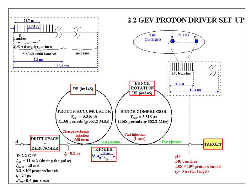
Figure 3.3 Accumulator Compressor scheme for a neutrino factory
In order to serve a neutrino facility, the 2.2 ms long pulse of low average current (11 mA) from the SPL needs to be converted into a train of short (1ns rms) bunches. The length of the train must be under the circumference of ~2 km of the muon storage ring. A ring fitting into the existing ISR tunnel (C=942 m, 15 m wide) is the natural choice for accumulating 1.5 x 10¹⁴ protons at 50 Hz. An initial attempt to design a single ring with a nearly isochronous lattice at 2 GeV (g = 3.1), capable to perform both accumulation and the bunch rotation with modest rf voltage, was discarded: It soon became clear that space charge causes blow-up of the <0.2 ns long linac micro-bunches, and requires high rf voltage for macro-bunch compression. Moreover, there is a strong non-linear effect of space charge on momentum compaction such that transition energy varies over the bunch.
Much more robust appears
a layout with two rings of high transition energy, separating
the functions of accumulation and bunch rotation, as depicted in Fig. 3.4.
Figure 3.4 The CERN reference proton driver: Accumulator/Compressor in the ISR tunnel. Grid size 30 m |
Microbunches then debunch quickly, space charge has little influence on the linearity of the lattice, and the high synchrotron tune in the accumulator produces a smooth distribution in longitudinal phase space, which is a good start for the rotation. The latter requires more rf voltage, but the critical issue of fast cavity filling is circumvented. The pre-detuned, filled, compressor cavities minimise transient beam loading. The ring parameters are listed in Table 3.3.
Table 3.3 Parameter List for the 2.2 GeV Proton Driver Accumulator-Compressor
| Parameter |
|
|
|
|
|
|||
|
|
|
|
|
|
|
|
|
|
|
|
|
|
|
|
|
|
||
|
|
|
|
|
|
|
|
|
|
|
|
|
|
|
|
|
|
|
|
|
|
|
|
|
|
|
|
|
|
|
|
|||
|
|
|
|
|
|
|
|
|
|
|
|
|
|
|
|
|
|
|
|
|
|
|
|
|
|
|
|
|
|
|
|
|||
|
|
|
|
|
|
|
|
||
|
|
|
|
|
|
|
|
|
|
For the proposed implantation
of the SPL on the site [13], part of the debunching
section and a 250 m long collimator achromat need also be installed in
the ISR tunnel. The accumulator ring is filled by H-
injection over 660 turns. Figs. 3.5a, 3.5b shows a superperiod of the accumulator
with a long dipole at the centre of a dispersion bump, which is absent
in the compressor lattice (Figs. 3.6a, 3.6b). This low-field dipole bends
the trajectory of the injected beam towards the foil with a minimum of
excited H0states.
The technique of ramping of the linac energy for horizontal 'painting'
by placing the foil at a point of large dispersion (anti-correlated with
a vertical orbit bump to produce a KV-like transverse distribution) has
been proposed for a number of high-intensity machines, notably ESS. With
an average of 4-5 foil traversals of the circulating beam, the carbon foil
temperature will not exceed 1800 K, a rather conservative value.
 |
 |
| Fig. 3.5a Structure of a Superperiod of the Accumulator | Fig. 3.5b Lattice Functions bH , bV and DH for one Accumulator Superperiod |
 |
 |
| Fig. 3.6a Structure of a Superperiod of the Compressor | Fig. 3.6b Lattice Lattice Functions bH , bV and DH for one Compressor Superperiod |
 |
 |
|
|
|
Amongst the effects of space charge and collective instabilities in the accumulator, only the microwave instability raises concern. Its calculated growth time of 0.6 ms for a broadband impedance of (Z/jn) = 1 W is of the order of the accumulation time of 2.2 ms. A more detailed simulation [17] predicts stability by Landau damping due to the tails of the distribution. Even the Laslett tune shift in the compressor at the end of bunch rotation is not more than DQ ~ - 0.2. In an earlier PDAC version, featuring only 12 bunches, an impressive DQ ~ - 2 had been calculated for maximum compression. This was considered acceptable in view of the short time for which this shift is active, but a weak horizontal halo appeared in tracking studies [18].
The study of the CERN Reference proton driver has shown that this scenario, which adapts the SPL to the original 44 MHz Muon Rotation and Cooling scheme, looks very promising. No major problems have emerged and in some respects its parameters are rather conservative. The study will continue focusing on the aspects that have not been studied yet or need refinement.
3.4 Other uses of the SPL
Although designed for the needs of a neutrino factory, the SPL can replace the present injectors of the PS and improve its performance. The location of the SPL has been carefully chosen for an easy transfer of the beam to the PS and ISOLDE with minimum civil engineering, as visible in Figure 3.2.
The present ISOLDE facility can be supplied with a beam which is up to 5 times more intense (up to 10 mA , limited by the present ISOLDE lay-out) and better matched to the target capabilities, without interfering with the PS needs. In a future stage, the next generation ISOL facility, which will need up to 100 mA, can also be accommodated.
The brilliance of the proton beam for LHC can be doubled. Unfortunately, this upgrade to the PS performance cannot be exploited for a luminosity improvement of the LHC in its present configuration. Thereason is that the present PS can provide the high-brilliance beam sufficient to reach the beam-beam limit in the LHC, resulting in the so-called ultimate luminosity of 2.3 x 1034 cm-2s-1. However, it is not inconceivable that a modified/upgraded LHC configuration might need a different beam from the PS for which the SPL would be a possible injector, though very likely much too powerful given the various limitations in the PS and SPS. As a matter of fact, the front-end of the SPL or an upgraded linac-2, providing a H- beam of 120 to 150 MeV would very likely be sufficient for the job. It would also provide a better operational margin for the PS in case the LHC can operate at the beam-beam limit.
The advantage of the SPL for the fixed-target programme has been studied, in particular for the CNGS operation [Cappi01]. It has been shown that the average proton flux can be increased between a factor 1.5 to 1.8 However, also in this case the full potential of the SPL is not used and an upgraded linac-2 or the front-end of the SPL would suffice.
In a staged approach, before the muon part of the neutrino factory is available, the 2.2 GeV / 4 MW proton beam from the accumulator or the compressor ring can also be used to generate a conventional neutrino beam from pion decay. The interest for physics of such an intermediate facility is being actively investigated (see Chapter xxx).
3.5 Rapid-Cycling Synchrotrons
3.5.1 The 30 GeV/8Hz Rapid-Cycling Synchrotron
This scenario is not
matched to the 44 MHz muon collection system (but a 40.27 MHz collection
system could handle the bunch structure from this proton driver). The driver
synchrotron, also using the ISR tunnel, is filled on a 2.2 GeV, 60 ms,
flat bottom by four batches of two bunches each from a 1/4-size 50 Hz booster
(similar to the AUSTRON RCS design [19]).
At the end of the booster cycle these bunches are pre-compressed to fit
into the buckets of a h=32 rf system of the driver, which accelerates the
eight bunches in 45 ms to top energy. The necessary peak voltage of 3.8
MV is delivered by 22 cavities of a novel design [20]:
An external mechanical tuner, coupled to the cavity by 31/8" cables produces
the required frequency variation of ~ 4%. Each cavity (L = 1.8 m, r/Q =
42 W
, Q = 5000-10000) should contribute 175 kV. The high peak rf voltage can
provide naturally short bunches without compression at top energy, if the
transition energy is chosen to be not too far above it, and if the vacuum
chamber impedance can be limited to (Z/jn) £
2 W
. The feasibility of the approach has been demonstrated by tracking studies,
including a broadband resonator or a set of equivalent high-Q resonant
longitudinal impedances. For a top energy of 30 GeV, the optimum gt
is ~40. A "resonant" lattice, similar to that proposed earlier for high
g-transition
values [21], was designed, which has excellent
dynamic apertures. It is by no means trivial to fulfil the needs for long
dispersion-free straight sections, chromaticity correction, limited dispersion,
and linearity of momentum compaction, when more than half of the circumference
is taken up with bending magnets. In fact, a limit to the quadratic term
½a1½£
0.01 of the momentum compaction was found by simulation. This condition
is in general not met by the resonant lattice, except for a region of partially-compensated
chromaticity around xx,z
~ 6, a value which is just acceptable. Nevertheless, an alternative, more
conventional, lattice of gt
~30, limiting the top energy to 25 GeV (still above transition of the SPS),
is being studied. Tables 3.4 and 3.5 summarise the main parameters of the
booster and the driver synchrotrons. A possible topology, where the complete
injector is inside the ISR tunnel, is shown in Figure 3.8.
Table 3.4 Booster Beam and Machine Parameters for the Alternative Scenario
|
|
|
|
| Kinetic energy |
|
|
| Pulse frequency |
|
|
| Pulse intensity |
|
|
| Number of bunches |
|
|
| Circumference |
|
|
| Nr. of injected turns (56 mA) |
|
|
| rf harmonic number |
|
|
| rf frequency |
|
|
| rf peak voltage |
|
|
| Space charge tune shift at inj. |
|
Table 3.5 Driver Output and Machine parameters for the Alternative Scenario
|
|
|
|
| Mean beam power |
|
|
| Kinetic energy |
|
|
| Pulse frequency |
|
|
| Pulse intensity |
|
|
| Number of bunches |
|
|
| Bunch length (1s ) |
|
|
| Momentum spread (2s ) |
|
|
| Transv. emittances, norm. (2s ) |
|
|
| Longitudinal emittance / bunch |
|
|
| Circumference |
|
|
| rf harmonic number |
|
|
| rf frequency |
|
|
| rf peak voltage |
|
|
| Transition energy gt |
|
|
| Tune shift on flat bottom |
|
Figure 3.8 The CERN 30 GeV, 8 Hz Proton Driver in the ISR Tunnel with its Injector. Grid Size 30m.
The study of the alternative
8 Hz synchrotron scenario will be complemented by the evaluation of a 25
GeV driver with a more conservative lattice, a more detailed assessment
of the coherent effects, and a study of halo development during the up
to 60 ms long stacking. The study will then be suspended. It will resume
if a future evolution shows that the RCS approach appears more promising.
3.5.2The 5Gev/25Hz and 15GeV/112.5Hz Rapid-Cycling Synchrotrons
Introduction
The ISIS Accelerator Group at the Rutherford Appleton Laboratory has
been actively collaborating with CERN on proton driver designs, target
geometry and construction, and the front end of a possible neutrino factory.
The proton driver work has concentrated mainly on the use of rapid cycling
synchrotrons but RAL has also contributed to the CERN scenario based on
a high energy superconducting linac feeding accumulator and compressor
rings.
Overview
Two sets of design
parameters are under consideration for the synchrotron-based models. The
first option (Driver I, Fig. 3.9) uses four proton bunches per pulse at
a final energy of 5 GeV and frequency of 50 Hz. The other (Driver II, Fig.
3.10) is at 25 Hz with six bunches per pulse at 15 GeV. Both scenarios
aim to provide 4 MW of beam power, though Driver II has the potential to
upgrade to 6 MW.
Figure 3.9 Layout of the 5
GeV, 50 Hz, 4 MW proton driver
The development of the designs has been influenced by two main factors. The aim is to generate final output bunches of high intensity and very short (1 ns rms) bunch durations at the pion target. Achievement of the required intensity, via accumulation in the rings, presents different problems from final bunch compression, and no satisfactory common solution has been found. Each synchrotron scenario therefore uses separate booster rings for injection and a first stage of acceleration, followed by main rings for acceleration to full energy and compression. The short final bunch durations require a small final longitudinal emittance of the order of only 1 eV.s if unacceptably high energy spreads are to be avoided. From the formula for longitudinal bucket area
![]()
A will be minimised if g , 1/h, and 1/|h| are minimised and hsc is a maximum. Here h is the slip factor 1/g2t-1/g2, a is the standard normalised Hamiltonian integral and
![]()
is the ratio of the longitudinal space charge voltage to the applied cavity voltage. An upper limit of hsc =0.4 is taken to avoid the microwave instability [23]. These conditions are most conveniently met with a low injection energy, and a value in the range 150-200 MeV is preferred.
In view of these considerations,
the scheme proposed for Driver I uses a 180 MeV H-
linac to
feed two 50 Hz, 1.2 GeV synchrotrons, operating almost in phase. The rings
are likely to be stacked one above the other. Together these feed in alternate
cycles two 25 Hz, 5 GeV rings, also stacked vertically. The combined output,
after bunch compression, is at 5 GeV and 50 Hz. The final energy of 5 GeV
has been selected for study as this is the lowest energy at which it appears
practical to achieve the specified final synchrotron bunch durations.
Figure 3.10 Layout of the
15 GeV, 25 Hz, 4 MW proton driver.
For Driver II, the basic scheme remains the same but the two booster synchrotrons are now at 25 Hz and 3 GeV, and the main rings at 12.5 Hz and 15 GeV, with a combined output at 25 Hz.
RAL also collaborates in the CERN scheme based on a 2.2 GeV superconducting linac feeding a large circumference accumulator ring and a separate compressor. ISIS Accelerator Theory Group performed the design of the accumulator ring [24]. Injection studies have been carried out, and a lattice suitable for the final bunch compression was also identified.
Injector Linac
Common to both drivers
is a 180.2 MeV H- injector linac operating at a current of 57
mA. The overall length is 129 m and the injector consists of a 2.493 MeV,
280 MHz radio-frequency quadrupole linac (RFQ), a chopper section and an
eight tank, 280 MHz Alvarez linac. A 3 MW peak power rf generator is required
by each of the eight tanks, including 25% additional power for field control.
The chopping section provides a 70% beam duty cycle at a sub-harmonic of
280 MHz which is close to the rf frequency of the booster rings at injection.
Levels of transverse space charge are acceptable and full modelling of
the linac has been carried out using the Los Alamos code PARMILA.
The beam line between the linac and rings provides some debunching of the linac microbunches, subsequent momentum reduction, collimation and ramping, and vertical beam separation for each booster synchrotron. Separate 280 MHz cavities are required for each stage. A four period, 41.6 m, achromatic collimator bends the H- beam through 180o and includes some reverse bends and two buncher cavities. The reverse bends enable the high normalised dispersion needed for momentum collimation to be achieved. A range of fractional momentum ramping up to 4 10-3 is provided for injection painting, with normalised transverse rms emittances of approximately 0.26 (p ) m rad.m.
Ring Injection,
Trapping and Acceleration
The use of booster and main rings allows the different requirements
of injection and bunch compression to be treated separately. Triplet lattices,
developed over a period of time for use in the European Spallation Source
(ESS) [25], are adopted for the boosters,
and provide both regions of high dispersion for injection and momentum
collimation, and long dispersion-free straights for the rf systems, betatron
collimation and fast extraction. The lattice functions and superperiod
structure for the booster of Driver I are shown in Fig. 3.11; those for
the booster of Driver II are similar. Booster I has three superperiods
and mean radius 32.5 m, and Booster II has four superperiods and mean radius
50 m.
Injection of the chopped beam is via an Al2O3
stripping foil in a low field dipole (~0.05 T) positioned at a point in
the rings where the normalised dispersion Dh/Öbh
is in the range 1.6-1.8. 160 turns are injected into Driver I over 200
m
s and 70 turns into Driver II over 134 m s.
The intervals are timed symmetrically about the minimum of an accelerating
sinusoidal wave-form B(t)=B0-B1sin(2p
ft). Thus injection is into a decelerating bucket at the start of injection
and into an accelerating bucket at the end. The rf cavity voltages are
carefully programmed so that the entire beam is injected into stable regions
of longitudinal phase space, particularly in the latter stages of injection.
Momentum painting of longitudinal phase space improves the accumulated
beam distribution and enhances the bunching factor.
 |
 |
Transversely, the distribution is controlled by four vertical orbit bump magnets and coupling of the momentum painting into the horizontal plane via dispersion. The system is optimised with the aim of reducing subsequent traversals of the stripping foil by recirculating protons, thereby avoiding excessive temperatures in the foil.
In order to permit
hands-on maintenance in the rings, low loss levels are required of the
order of 10-3.
Some of this is accounted for by H- and proton interactions
with the foil, making it important that further losses, which occur mainly
during trapping in the first stages of acceleration, are avoided. This
is achieved using a suitably programmed system of rf voltages, with an
rf frequency range allowing limited radial steering after injection. A
single harmonic h=2 system with maximum peak voltage![]() =
0.28 MV is used in Booster I, while Booster II has h=3 and
=
0.28 MV is used in Booster I, while Booster II has h=3 and ![]() =
0.4 MV. Two bunches each of 2.5 x 10¹³
protons and three of 1.11 x 10¹³
protons are accumulated in the boosters respectively. At ejection, the
respective bunch durations are 100 ns and 50 ns.
=
0.4 MV. Two bunches each of 2.5 x 10¹³
protons and three of 1.11 x 10¹³
protons are accumulated in the boosters respectively. At ejection, the
respective bunch durations are 100 ns and 50 ns.
Final Bunch Compression
For each driver, the bunches in the two vertically-stacked booster
rings are extracted and transferred together to either the upper or the
lower of the two main synchrotrons in alternate cycles. Each transfer line
contains a pulsed dipole magnet to provide vertical beam splitting.
The requirements of the final 1 ns rms bunch compression have, to a
large extent, dictated the main ring designs. Separate simulation studies
indicate that the compression can be achieved by working close to transition
energy. Crossing transition and subsequent instabilities need to be avoided;
thus the lattice requirement that g approaches
from below to within about 5% of gt
at top energy has been adopted. As the bunches compress, however, gt
will in general be reduced, and there is a risk that transition may be
crossed nevertheless. A feature of the ring design is therefore that transverse
space charge tune shifts are small and the dispersion functions resist
depression of gt. Simple doublet
lattices have been adopted and the shape of the resulting dispersion function,
the b -functions and the superperiod structure
for Driver I are shown in Fig. 3.12. Here the effect of over 1200 A of
beam current is merely to depress gt
from 6.50 to 6.47. Inductive impedances |Z/n|~5-10 W
are envisaged for the metallic and ceramic vacuum chambers to help reduce
longitudinal space charge effects.
 |
 |
Acceleration is achieved
by cavities with programmed rf fields. For Driver I, where the rings contain
four bunches, these use harmonic number h=8 with maximum ![]() =
0.575 MV, providing some compression. Additional h=24 cavities are
brought into play over the last 1 ms of the cycle to reach the 1 ns rms
duration required. The peak total voltage necessary from these additional
cavities is 0.5 MV. Simulations show a final bunch with peak momentum spread
Dp/p~1.6%
and longitudinal emittance eL~1.0
eV.s. In the case of Driver II, h=36 cavities with
=
0.575 MV, providing some compression. Additional h=24 cavities are
brought into play over the last 1 ms of the cycle to reach the 1 ns rms
duration required. The peak total voltage necessary from these additional
cavities is 0.5 MV. Simulations show a final bunch with peak momentum spread
Dp/p~1.6%
and longitudinal emittance eL~1.0
eV.s. In the case of Driver II, h=36 cavities with ![]() rising to 1.7 MV in mid-cycle, then falling to 0.6 MV, give similar results
with the final conditions achieved from adiabatic bunch compression.
rising to 1.7 MV in mid-cycle, then falling to 0.6 MV, give similar results
with the final conditions achieved from adiabatic bunch compression.
A consequence of working close to transition with a final Dp/p of this magnitude, is that second order momentum effects need to be taken into account. These contain both kinematic and path-length components. Whereas in the CERN 2.2 GeV compressor ring the first dominates, both effects are equally important in the RAL synchrotron-based proton drivers. However, it turns out that over-compensation of the path-length components can lead to simultaneous correction of the kinematic terms, and that this can be achieved through use of the sextupole magnets installed to correct the chromaticities.
Summary
A summary of the main parameters of the two RAL drivers is given in
Table 3.6. The initial study of both scenarios is complete and remaining
work on the drivers will rely on the use of three-dimensional tracking
codes for refinement of the systems.
Table 3.6 Parameters of the RAL Synchrotron Drivers
|
|
|
|
| Booster synchrotrons: | ||
| Kinetic energy (MeV) |
|
|
| Number of bunches |
|
|
| Bunch intensity |
|
|
| No. injected turns |
|
|
| Injection period (m s) |
|
|
| Mean radius (m) |
|
|
| g -transition |
|
|
| Normalised dispersion Dh/Öbh at foil (m½) |
|
|
| Qh, Qv |
|
|
| Harmonic number |
|
|
| Peak rf voltages (MV) |
|
|
| Main synchrotrons: | ||
| Kinetic energy (GeV) |
|
|
| Number of bunches |
|
|
| Mean radius (m) |
|
|
| g -transition |
|
|
| g |
|
|
| Qh, Qv |
|
|
| D Qh, D Qv |
|
|
| Chromaticities |
|
|
| Harmonic numbers |
|
|
| Peak rf voltages (MV) |
|
|
3.6 Comparison of Proton drivers
As it cannot be excluded that the calculated pion production at 2.2 GeV needs to be corrected in view of the results of the forthcoming HARP experiment [10] at the CERN PS, a higher beam energy of 5 - 30 GeV may be desirable. Actually, the approach of having a chain of "Rapid Cycling Synchrotrons" (RCS) is generally considered to be more economic than the combination of high-energy linac plus accumulator ring. Linac energies not exceeding 150180 MeV facilitate the handling of the rf capture loss, which is very difficult to suppress completely. This approach has been pursued in the RAL scenarios in a site-independent optimization.
For a CERN-specific
scenario, a driver synchrotron of 25-30 GeV is desirable, as this machine
could inject into the CERN SPS above transition energy, substantially upgrading
its performance for fixed target physics [16].
Whether it could also be useful for the proton and ion programmes of the
LHC needs further study. ISOLDE would profit from the 440 kW beam
power of the 2.2 GeV booster synchrotron. Table 3.7 compares the parameters
of the different drivers and lists the critical features.
Table 3.7 4 MW Proton Drivers and their Bunch Compression Technique studied at CERN and RAL
|
|
|
|
||
|
|
|
|
|
|
|
|
|
|
|
|
|
|
|
|
|
|
|
|
Compressor |
2 RCS 5 GeV/25 Hz |
2 RCS 15GeV/12.5Hz |
1 RCS 30GeV/8.3Hz |
|
|
|
|
|
|
|
|
|
|
|
|
|
|
|
in 3 harmonics |
1.7 MV |
3.5 MV |
|
|
Bunch Rotation in 7-8 turns |
at end of Cycle, Bunch Rotation |
|
Adiabatic Compr. for Z/jn < 3 W ! |
|
|
|
Rotation delicate |
DQ dependence of a1. |
|
Figure of Merit
Comparison of the
various drivers from a target perspective is offered by a crude figure
of merit given, for a proton driver of fixed power, by the product of the
output energy and the repetition rate. As Table 3.8 shows, this suggests
some bias towards the 15 GeV option, which at this stage of the study is
the RAL preference. A further advantage of Driver II is that the main ring
would fit into the existing CERN ISR tunnel.
Table 3.8 Comparison of Proton Drivers
|
|
|
|
|
| CERN SPL+rings |
|
|
|
| RAL Driver I |
|
|
|
| RAL Driver II |
|
|
|
| CERN synchrotron |
|
|
|
4 Target Station and Support Facility
4.1 Description
A target station in which pions are abundantly produced in order to serve as precursors of muon neutrinos is described. It consists of a complete high level radioactivity laboratory with the technical support equipment needed to operate and service the high power production target, the spent beam absorber and the first particle collection and focusing device.
It is planned to build the target station in a modular way so that its individual parts can be rapidly replaced and serviced by means of remote handling. This should allow flexibility in the choice of equipment and allow a stepwise approach in which lower power conventional techniques are used in an early phase and later exchanged against more performing high power targets when developed. It will also permit the use of the well-established ISOLDE type techniques for production of intense beams of short-lived beta-unstable nuclei. In this way the neutrino factory could offer beams of pure electron neutrinos with precisely known energy spectrum derived from stored beams of radioactive nuclei as recently suggested by Zucchelli [Zucchelli01].
The deleterious effects on this equipment and its surroundings caused by the megawatt-scale power and radiation dissipated by the high intensity proton beam is the major challenge which identifies the target and pion capture system as one of the most crucial item of the neutrino factory. A molten metal-jet target located inside the neck part of a magnetic horn for pion collection has been chosen as the scenario for further investigation of the CERN muon neutrino factory production system. The tentative layout of such a system is shown in Figure 4.1 [Ravn01] and will be described in detail below. The system is quite similar to the scenario chosen by the US partners in the Muon Collaboration who favor a 20 T super-conducting solenoid as pion collector [Kirk00].
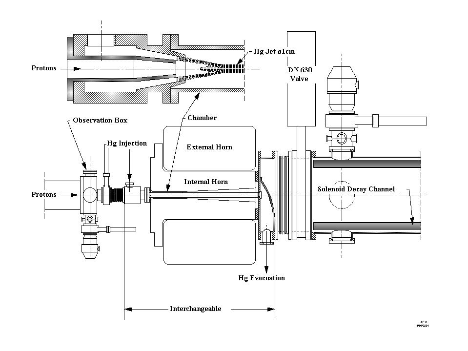
Figure 4.1 Layout of a target and magnetic horn-module in which a spray of Mercury is directed into the neck region of the horn. The Hg is injected via an annular nozzle that allows coaxial injection of the proton beam. Also indicated is the double horn structure that serves to reduce the stress on the critical neck region.
4.2 Pion production system
4.2.1 Description
The generation of pions in targets at high power presents or even exceeds the similar problems that are considered in a number of other planned facilities where it also is intended to use intense proton beams for the production of radioactive species. The spallation neutron sources, [Bauer96, Mansur01], accelerator production of tritium (APT), and transmutation of radioactive waste (TRW) may ease their heat transfer problem by depositing the beam power in large amounts of target material. However, the neutrino factory, like the planned facilities for acceleration of radioactive ion-beams (RIB) needs orders of magnitude smaller volume targets in order to efficiently release the charged particles to be captured and accelerated. The key problem is the initial pressure waves induced in any condensed matter by the ms short proton pulse, which deposits about 100kJ. They eventually exceed the yield strength of any solid target or tubes containing liquid ones and cause them to break down mechanically after short time.
New innovative techniques may be needed in order to dispose of the power generated in the small volume of a pion production target where local densities of up to 100 kW cm-3 may be encountered. At present two concepts seem to be viable in which either solid or liquid metal target material is re-circulated rapidly in the beam.
A number of such ideas which were presented at
the NuFact99 workshop [NIM00]
are now under laboratory tests in order to verify the simulations and determine
engineering parameters. They should in principle allow the use of pulsed
proton driver beams with 4 MW average power and may possibly be extended
to 20 MW but a considerable R&D effort is needed in order to select
the future directions among the many ideas around.
In addition, recent ideas of more conventional
technique of direct water-cooled granular metal target have received attention
[Sievers01]. The thermally induced shocks are expected to be grossly reduced
in the small granules (Spheres of 2 mm diameter, see Figure 4.2) and the
high power densities can be handled by an efficient water cooling, owing
to the high surface to volume ratio of the ensemble of the granules. Also
a high power Helium gas cooling circuit may be envisaged. This solution
may provide only limited performance and lifetime of the target but can
be useful as a first approach at initially lower beam powers. In any case,
the crucial problems are heat transfer, material stress, fatigue, radioactivity,
radiation damage, in particular of the front and end windows of the target
container and cooling media confinement.
| Place holder for Figure 4.2 |
4.2.2 Molten metal jet principle
Since equipment and expertise on liquid metal technology already exists at CERN and has been chosen by the majority of the above mentioned similar projects we believe this is the most promising direction. The essential feature of the jet is that it is rapidly reformed after each proton pulse that only scatters the liquid due to the above mentioned thermal expansion wave. Like in the spallation neutron sources, the metal Mercury has been chosen as the most promising high Z target and coolant material which could be replaced by several other metals or alloys including low Z elements. The following other advantages of a Hg-jet target should be noted:
In addition a static Hg filled test chamber with a high speed digital camera often referred to as the thimble test has been constructed for systematic on-line tests in the 1.4 GeV ISOLDE beam. Due to scheduling constraints the in-beam tests with this chamber was first done in the 24 GeV BNL beam within the Muon Collaboration experiment E951 [Fabich00]. As seen from Figure 4.3 the disruption of the metal bath already noted in ISOLDE Pb targets [Lettry97a] could be confirmed and recorded. It was performed with only a few proton bunches and gave valuable data on in beam Hg handling and proton beam induced pressure wave propagation in a liquid metal.
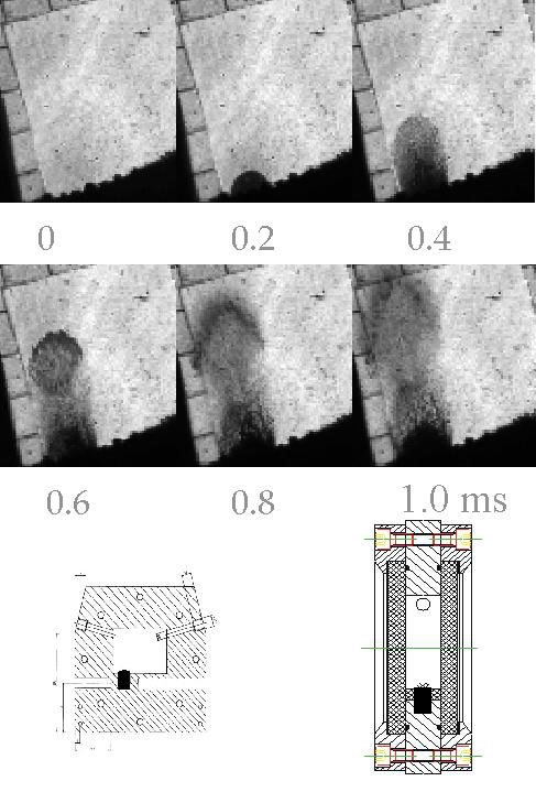
Figure 4.3 Reaction of a ~1 cm3
thimble partly filled with Mercury to the impact of a 24 GeV proton
bunch of 4.0 1012
and 100ns duration. The picture series shows that within 1 ms the
Hg is ejected as
a fountain when hit by the protons entering at
the lower left corner where also the thimble is located.
The insert shows a drawing of the test chamber
where the Hg is marked as a black rectangle.
This experiment was followed by on-line tests of a scaled down version of the Hg-jet in the BNL test beam. The series of pictures displayed in Figure 4.4 shows the break up of the free flowing Hg-jet as result of one proton bunch impact. The data, which still is in the analysing stage, suggests the following tentative conclusions. There is no visible propagation of the expansion wave in the axial jet direction outside the short length of maximum power deposition. The droplet speeds was lower than in the thimble test (~20 m/s) but seemed over the short intensity range studied to be proportional to the number of protons in the bunch.
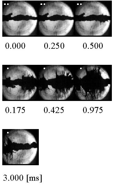
Figure 4.4 The picture series shows the break
up of a Hg-jet coaxial to the proton beam both entering from the right.
The jet parameters were: Diameter ~ 1cm and jet-velocity
~ 3 m/s.
The proton beam parameters were 24 GeV, 3.8 1012
ppb, 100 ns and diameter 2mm
In conclusion the BNL-CERN thimble and jet test at 1/100 of the ultimate power density and 1/10 of the needed jet speed revealed no showstopper for the Hg target concept.
4.3 Pion collection system.
4.3.1 Description.
In order to maximize the secondary pion collection efficiency the target needs to be surrounded by a large acceptance pion collection and focusing system. This device is further complicated since the spent beam absorber may need to be located in there.
4.3.2 Super conducting solenoid.
In the US projects the pion capture is suggested to be based on the utilization of a 15 cm bore, 20 T peak field super conducting solenoid which has the advantage of providing adequate space for the metal jet and its plumbing. The 20 T field is followed by a long section, where the field decreases adiabatically from 20 T to 1.25 T [Weggel99] and the beam pipe dimension increases to 60 cm diameter. The effect of the field reduction of a factor sixteen is translated into an increase of the beam radius by a factor of four, but also into a reduction of the same amount for the transverse momentum. In fact, if the longitudinal component of the B field follows a slow reduction along the z axis according to Eq. 4.1:
where B0 = 20 T and a is the adiabatic parameter. One can show [Jackson75] that the magnetic flux across the transverse orbit is conserved (namely Br2= const), and the angular momentum is also conserved (namely B/pt2= const).(4.1)
4.3.3 Magnetic horn
Since one is interested in the production of
one sign of pions for any given proton bunch, it could be envisaged to
use a pion collection system based on the azimuthal magnetic fields generated
between the coaxial conductors of a magnetic horn. This technology traditionally
used at CERN for focusing secondary particles [VanDerMeer61]
has the advantage that the parts exposed to the beam are rather simple,
inexpensive and can be radiation hard. The horn should be designed to focus
particles emitted at large angle, and with a momentum range of 200-400
MeV/c, from a target of a diameter of 20mm. The horn design will be rather
different from those used for high-energy beams, such as CNGS [CNGS98]
and NuMI. In fact, the horns for conventional neutrino beams focus pions
or kaons point-to-parallel because one is not particularly interested in
the spot size dimension at the exit of the focusing system, while a transverse
momentum reduction is more relevant for the final neutrino beam spot size
at the detector site. In the case of the Neutrino Factory, the beam coming
from the horn enters directly into a 60 cm diameter solenoid of the decay
channel. The beam emittance has to be small, which means both the radius
and the divergence have to be as small as possible at the same time. The
particular shape of the horn takes into account the need of this double
function.
The horn [Ball99] is compact in the longitudinal dimension (1 m), while the large radial dimension is quite remarkable compared to traditional designs. This choice was dictated by the particular pion spectrum produced by the 2.2 GeV proton beam. Most of the useful particles exit the target radially, with a typical transverse momentum of 250 MeV/c. One needs to bend these particles as soon as possible, which means a small radius of the horn neck, and for a long transverse distance. Since the field decreases as 1/R, where R is the distance between a point in space and the horn axe of symmetry, the focalization effects decreases also with the distance. The maximum current is fixed by mechanical and thermal constraints; reduction of the pulse length and thus of the horn inductance is finally a key condition to maximize the current. Limiting the magnetic volume limits the inductance of the device; a good solution is then to split the horn into two radial sections. In the inner horn section with a triangular shape flows a current of 300 kA. This part focalizes most of the low energy particles and the high-energy pions emitted at small angles. The outer horn section which is a hollow cylinder surrounding the first horn is excited by a current of 600 kA. The higher field generated at large radii captures the high-energy pions leaving at large angles. The performance of this horn is currently under study, but as preliminary results, the collection efficiency is comparable to the 20 T solenoid.
A preliminary technical study of the 1m long triangular shaped horn pulsed at 50 Hz has been started [Maugain80].
Limiting factors for this technology are found
in the waist region of the inner conductor. It needs to have a diameter
of minimum 5 to 8 cm in order to accommodate the target and its plumbing.
The Joule losses in a waist of this diameter raises concerns about cooling
followed by the lifetime limitation caused by the magnetic forces of the
high current pulse and the possible weakening of the material caused by
radiation damage.
A new cooling system is shown in Figure 4.5,
where the traditional conductor is divided into three skins. The first
skin is Al without any current; the second is a water flowing layer, which
cools the inner and third layer of Al where the current flows. A good compromise
between the radial dimension of the conductors, the water channels and
supports and the pion absorption is still under study. Usual water spraying
of the third current carrying layer (i.e. inner conductor) is kept in addition.
A cooling water flow between the inner conductor at high voltage and the
target chamber is prohibited due to the need of electrically insulation.
A third possibility of pion collection [Autin01],
is to send a high current pulse directly through the molten metal-jet target
so that it also acts like a Lithium lens. Since the Joule losses were found
to be comparable to the beam heating this method might require unrealistic
high metal-jet speeds.
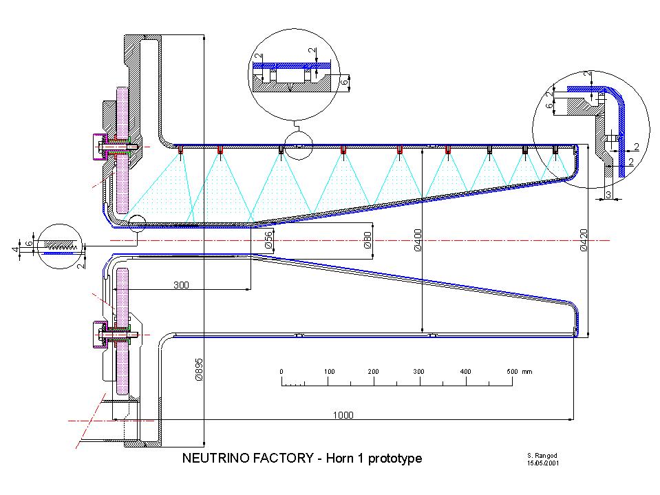
Figure 4.5. Horn with special cooling for testing
at 50Hz repetition rate. ISAC target plugs.
4.4 Radioactive ion production system
4.4.1 Description
The generation and extraction of short-lived radioactive ions which may be useful as precursors for intense, pure electron-neutrino beams is a well-known technique used in various Radioactive Ion-Beam (RIB) facilities mainly in Europe. A method very similar to pion production of in-flight capture of charged heavy-ion fragments presently dominates as production method for high energy radioactive ion beams of the rare most short-lived nuclear species.
However, when it comes to production of high intensity beams of radioactive nuclei the technique of target fragmentation by means of an intense proton or neutron beam as practiced at ISOLDE [Ravn79] is the method of choice. Such a facility based on the Isotope Separator On-Line technique (ISOL) allows to use very thick targets in which the fragments are brought to rest before they are re-ionised and accelerated.
An intensive program for further development of this technique for present and future RIB facilities is actively being undertaken by the EURISOL collaboration [EURISOL]. The possibility of using the MW power of future GeV proton driver accelerators for a RIB intensity increase of 103 has already been assessed. For the nuclei relevant to a neutrino sources which are formed in high cross-section reactions with half-lives in the range of 100 ms to 10 s the prospects are particularly promising.
This method for production of electron neutrinos has the following technical advantages over the method for production of muon neutrinos:
As an example the principles and electron
neutrino intensities which may be obtained from such an ISOL target station
optimised for production of 6He and 18Ne as proposed by Zuchelli [Zuchelli01]
is discussed below.
4.4.2 Target Station for production of intense beams of short-lived beta emitters
A target station based on the ISOL technique [Ravn98] consisting of a target and ion source unit remotely coupled to a front end which contains the beam extraction and focusing elements is illustrated in Figure 4.6.
| Place holder for Figure 4.6 |
The nuclide of interest is produced by proton fragmentation of a refractory target kept at high temperature and thick enough to stop the fragments. By means of diffusion and desorption processes the isotopes of the element in question are released and transferred to an ion source as shown in Figure 4.8. The source emittance is typically in the range of 2 to 50 pmm mrad. By means of a 60 kV extraction field the singly charged ions are accelerated and may subsequently be electromagnetically mass separated into beams of its individual isotopic components.
| Place holder for Figure 4.8 |
The very asymmetric pulse shape of the resulting ion current shown for the two rare-gas elements Helium and Neon in Figure 4.9 is not determined by the proton bunch and the nuclear reaction but by the relatively slow thermal release and transfer processes [Ravn97, Lettry97b]. This function also controls the usually largest loss factor the half-life dependent decay loses occurring during the release and transfer processes.
| Place holder for Figure 4.9 |
The radioactive beam intensity that may be obtained from such a target station is determined by Eq. 4.2
where s is the formation cross-section for the nuclear reactions of interest, F the primary-beam intensity, N the usable target thickness, e1 the product release and transfer efficiency, e2 the ion-source efficiency and e3 the delay transfer efficiency due to radioactive decay losses.I = s F N e1 e2 e3, (4.2)
4.5 Spent beam absorber
The pion production target absorbs only 25% of the 4 MW beam power while the remaining beam needs to be absorbed in a suitable beam stopper which could be accommodated in the downstream part of the horn. Although similar heat transfer techniques as used in the target may be used the material and cooling of the dump has to be studied in view of a low Z material. An alternative could be a Carbon Iron assembly cooled by Helium and water. However, it is not an ideal location since apart from increasing the complexity of the horn it also will absorb some pions. A location somewhere after the decay channel is under study but no satisfactory solution has been found yet.
4.6 Target station and support laboratory
The housing and operation of the above mentioned
equipment requires a substantial laboratory infrastructure very similar
to what is found in the planned spallation neutron sources ESS [Bauer96]
and SNS [Mansur01].
In order to assure a staged approach to more and more powerful target techniques
as well as to allow frequent service a modular system in which individual
components can rapidly be exchanged by remote control is envisaged. Such
systems have been used at ISOLDE and constructed for high intensity use
at the ISAC project at TRIUMF. In this system [ISAC] the in-beam equipment
is mounted at the bottom of a long plug as seen in Fig. 4.7. These plugs
are loaded into the beam tunnel from above. The plugs have enough shielding
to allow hands on work at its upper end when the beam is off. The plugs
may now be transported to storage locations or maintenance hot cells via
the crane bay that forms the third floor in the target station as seen
in Figure 4.8 [Spaminato00].
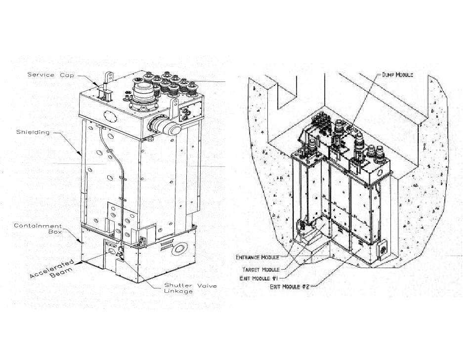
Figure 4.7 ISAAC target plugs
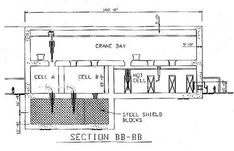
Figure 4.8. Principle of top loading active equipment
into the beam tunnel or the hot cells.
4.7 International collaboration
The contacts to the community of people and laboratories outside CERN who has expressed interest to participate in a variety of high power target, pion collection and beam-dump developments is maintained and is being extended to new laboratories. At present only collaborations with BNL, LCMI Grenoble and RAL are actively producing data.
4.7 Conclusion and future work
A target and horn working-group has been formed at CERN in which many of the skills needed for designing a 4MW target station are represented. Laboratories for molten metal technology and horn development have been set up. Experiments aimed at determining crucial engineering parameters that will allow choosing among the various proposed technologies have started. A satisfactory solution to the location and type of the beam dump without causing excessive losses of muons remains to be found. This stopper should neither cause excessive losses of muons nor produce an unnecessary high amount of radioactive waste. Within the existing resources a program for further development of the chosen concept has been setup. On the experimental side the program looks as follows:
| Place holder for Table 4.1 |
5 Layout of the front end of the Decay and Cooling section
5.1 Introduction
After the target pions decay in a 30m long channel focussed by a 1.8 Tesla solenoid, with a transverse radius of 30 cm. At the end of the decay channel the particles with kinetic energy in the range 100-300 MeV are captured in a series of 44 MHz cavities and their energy spread reduced by a factor two. At this point a first cooling stage, employing the same rf cavities, reduces the transverse emittance in each plane to 60% while keeping the average energy constant. After the first cooling stage the beam is accelerated to an average energy of 300 MeV. At 300 MeV the beam in injected into a 88-MHz cavity cooling system. where rematching cells are periodically inserted to control the longitudinal dynamics. At the end of the second cooling stage the emittance is reduced by a factor 4 in each transverse plane [36]. The system is continued at 88 MHz, and 176MHz until the final energy of 3 GeV -suitable for injection in a µRLA- is reached. The system works also with 40 MHz, 80 MHz, 200 MHz. The general layout is presented in Table1
Table 5.1 Components of the 40-80 MHz scheme and their characteristics
| Decay | Rotation | Cooling I | Accel | Cooling II | Accel | |
| Length, m | 30 | 30 | 46 | 32 | 112 | ~450 |
| Diameter, cm | 60 | 60 | 60 | 60 | 30 | 20 |
| B-field, T | 1.8 | 1.8 | 2.0 | 2.0 | 2.6 | 2.6 |
| Frequency, MHz | - | 40 | 40 | 40 | 80 | 80-200 |
| Gradient, MV/m | - | 2 | 2 | 2 | 4 | 4-10 |
| Kinetic Energy, MeV | - | 200 | - | 280 | 300 | 3000 |
5.2 Beam dynamics in
the front end
A pion beam was generated
(program FLUKA) from a 2.2 GeV proton beam (dp/p=1.2 10-2,emittx=50m
m) instantly impinging on a 26 mm mercury target immersed in a 20 Tesla
solenoid. The data were extrapolated (linearly) to a 260mm long target.
These particles were used for all the simulations presented here also if
further optimisation of the target and the subsequent focussing system
have advanced.
The beam dynamics of pions-muons system from the decay channel until the injection in the µRLA was studied with the program PATH (CERN version).
All the particles produced from the target were tracked through the system, cuts in longitudinal phase space have been made at the interface of each section for the sake of clarity in the presentation.
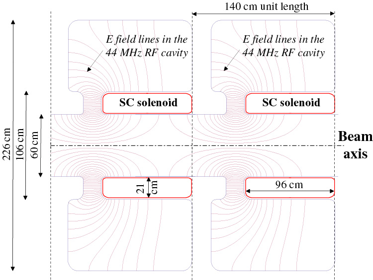
Simulations have been performed with idealised Rf cavities, in particular the 44 MHz cavities for phase rotation and cooling have been assumed to be 1 m in length and the 88 MHz cavities have been assumed to be 0.5 m long. Provided the gradient and the bore aperture are kept (2 MV/m , 30 cm at 44MHz and 4MV/m, 15 cm at 88MHz) the cavity geometry (gap length, total length, shape) can be modified without fundamentally affecting the results reported in the following. A different cavity shape involves some re matching of the transverse plane as the distance between adjacent solenoids is probably bound to change. This allowed the parallel development of an optimized rf structure which provides the requested gradient but has different geometry than assumed in the beam dynamics calculations (see chapter by Roland Garoby)
The decay channel input and output longitudinal and transverse phase space are reported in figure 5.1. Work has started towards limiting the emittance increase during the decay process in a magnetic field. (factor almost 1.5 in the case presented)
Figure 5.1-Longitudinal and transverse
phase planes at the input and output of the decay channel.
Only a subset of the muons surviving at the end of the decay channel can be captured in a rf structure because of the enormous energy spread. Assuming a realistic gradient of few MV/m, and in order to keep the phase rotation section within a length of approximately 50 m only the particles within an energy spread of 100 MeV can be successfully captured. The slow muons (kinetic energy lower than 100 MeV) de-bunch faster than a 2MV/m field can rotate them and thus they can't be succesfully rotated if we assume a limit gradient of 2 MV/m. Shall future rf tests demonstrate a higher field avaliable at 40 MHz, the system could be sligltly reviewed.
| Energy
spread
(average energy MeV) |
± 50 MeV | ±100MeV |
| 150 | 4.7° | 12.7° |
| 250 | 1.4° | 3.3° |
| 350 | 0.6° | 1.4° |
For the reference scheme
the phase rotation system is optimised for muons with kinetic energies
between 100 and 300 MeV (kinetic). More than 50% of the muons arriving
at the end of the decay fit in the energy acceptance of the phase rotation
system. This fraction can't be improved -unless pions are pre-rotated immediately
after production. A set-up composed of 30 1 m long 44 MHz cavity at 2 MV/m
and an aperture radius of 30 cm with a solenoid around the vacuum chamber
has been employed, giving the results reported in figure 5.3. The cavities
don't need to be closed with a beryllium window : particles have been tracked
through a calculated field with and without windows showing little difference
in the outcome. The rotation is very slow (3 degrees per cell, thus containing
the transverse emittance increase to some 10%).
At the end of the
phase rotation the beam has still a structure on 44 MHz and it can be cooled
without previous bunching. The fundamental cooling cell (figure 5.4) is
composed of four 44 MHz cells and 24 cm of hydrogen; the solenoid is fitted
around the gap of the rf cavity and covers almost uniformly the cell. Preliminary
SUPERFISH runs confirm the feasibility of this structure. The distortion
in the longitudinal phase space caused by sinusoidal variation of the rf
can be tolerated as the field gradient is small compared to the energy
spread.
|
24 cm gap
|
|
|
|
H2 |
The energy loss/gain
per cell is 5.6 MV. The process is applied 11 times and the emittance is
reduced by 60% in each transverse plane. The beam is then accelerated to
an average energy of 280 MeV by the same set-up (without absorbers): this
accelerating section provides also some re-bunching and matching to the
next cooling section. A good fraction of the beam (65% at the moment, but
it can be improved) at the end of the first stage of acceleration fits
in a 88 MHz bucket. The cooling process can be continued with 88 MHz cavities
0.5m long at 4 MV/m and 15 cm aperture radius. The 88 MHz fundamental cooling
cell (reported in figure 5.5) is composed of eight 50 cm long 88 MHz cells
and a 40 cm long Hydrogen absorber; a solenoid is fitted around the bore
of each cavity. The longitudinal beam phase space along the 88 MHz cooling
channel is reported in figure 5.6. The final beam phase space is reported
in figure 5. 7. The fraction of muons within the 6D recirculator acceptance
meets the specification of the neutrino factory as reported in the next
section. After the beam is cooled, the system is continued with 88 MHz
cavity of the same type until the beam has reached 1 GeV when a transition
to 176 MHz is possible.
|
0.5 m |
|
|
|
|
|
|
|
H2 |
Figure 5.6 - Longitudinal beam phase space along the 88 MHz channel. |
 |
 |
5.3 Particle budgetFigure 5.7 The transverse and longitudinal phase space at the end of cooling. The ellipse area are 1.5p cm rad for the transverse and 150 p mm dp/p (normalised) for the longitudinal
The particle budget as calculated by PATH with hard-edge model for the electric and magnetic field is reported in figure 5.8. A 20% losses should be added due to muon decay.
Figure 5.8 Pions -muons budget along
the channel
Assuming the particle production as predicted by FLUKA (0.2 p+/proton at 2.2GeV) the yield of the system is 0.42 % m+/protonGeV including the muon decay. Assuming the proton flux of the CERN Superconducting linac and accumulator ring this would result in some 1021 µ/year (1 year = 107 sec) delivered into the acceptance of the muon re-circulator.
5.4 The technical challenges and an estimate of the rf power needed
The underlying motivation for this set-up is to
make use of hardware with little extrapolation from existing technology.
Based on experience with 40 MHz CERN-PS cavities
[21] and analysing with SUPERFISH the characteristics
of resonator geometries that could fit the needs of the muons sections,
encouraging results have been obtained. Figure 5.9 shows a typical assembly,
with a bore radius of 30 cm and a solenoid fitted inside a cylindrical
volume
of 22 cm width. A real estate gradient of 2 MV/m at 44 MHz is obtained
with a peak rf power of 1.86 MW per cavity [?].
 |
rf characteristics |
|
| E0T | 2 MV/m | |
| ZTT | 3 MW/m | |
| R/Q | 103 W | |
| Filling time | 296 ms | |
| PPEAK | 1.86 MW/cavity | |
| PMEAN (50 Hz) | 89 kW/m | |
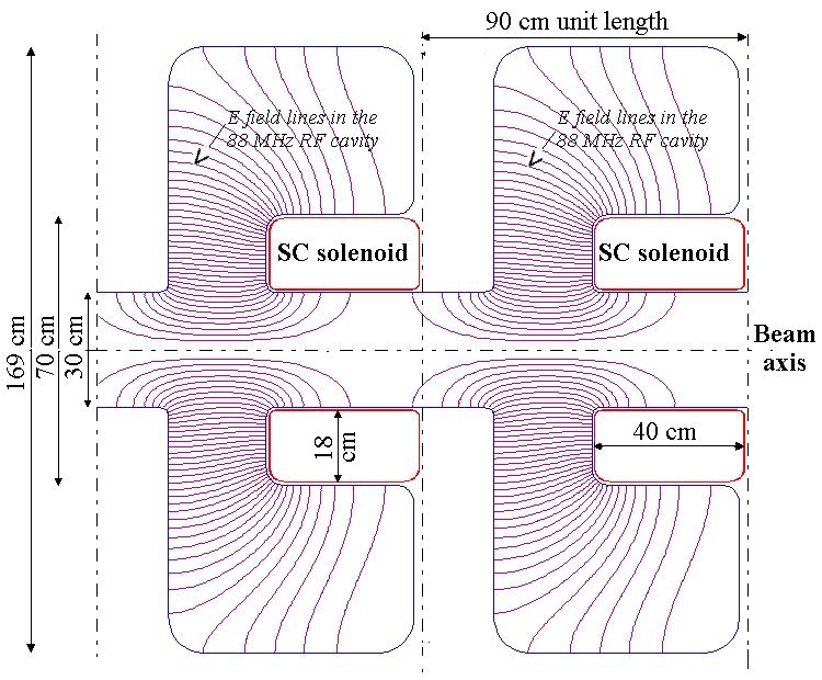
With a similar design at 88 MHz and having a bore
radius of 15 cm (see Figure 5.10), a real estate gradient of 4 MV/m is
achieved with a peak rf power of 2.04 MW per cavity.
 |
rf characteristics |
|
| E0T | 4 MV/m | |
| ZTT | 7 MW/m | |
| R/Q | 144 W | |
| Filling time | 159 ms | |
| PPEAK | 2.04 MW/cavity | |
| PMEAN (50 Hz) | 81 kW/m | |
The mean rf power consumption to operate all the 200 m of the Rotation and Cooling sections at 50 Hz is consequently estimated as 19 MW.
The performance of the overall scheme, as well as the construction (physical length) and operating costs (electricity consumption) depend heavily upon the characteristics of the rf systems. Since these systems operate in unconventional conditions, R. and D. is especially important, particularly on the following subjects:
5.5 The dependence on the proton beam time duration design
The basic idea of the reference scheme is to make use of the pions beam microstructure to avoid re-bunching before cooling, the impinging proton beam longitudinal structure has an influence on the overall performance. We can see from fig 1 that the intrinsic spread due to decay and path length through the solenoid is of the order of naseconds so a proton beam bunch length below that value would not help. In table 5.2 the relative performances at the end of cooling for a square and for a gaussian proton pulse are reported. An rms bunch length of 1 nsec (3nsec total) would be welcome. This value is achievable [26] as the number of microbunches is virtually unlimited and the space charge per bunch can thus be lowered to allow such a tight compression.
Table 5.2 Muon yield vs. proton bunch length for a square and for a gaussian pulse
| Proton pulse total length (nsec) (square pulse) | m /year (1021) |
rms length (nsec) |
Relative yield | |
| 0 | 1.6 | 0 | 100 | |
| 1 | 1.5 | 1 | 89 | |
| 2 | 1.4 | 2 | 80 | |
| 3 | 1.3 | 3 | 73 | |
| 4 | 1.2 | |||
| 5 | 1.1 | |||
| 6 | 1.1 | |||
| 7 | 1.0 | |||
| 8 | 0.98 | |||
| 9 | 0.97 | |||
| 10 | 0.93 |
5.6 Muon front end without cooling
The possibility of a muon front-end without cooling was examined [27]. In particular a study was performed on a system exactly like the one described above with the exception of the absorbers, which were removed everywhere. This ensures the compatibility of the two options and it gives an estimate of the yield for a potential staging of the front-end. The extra rf power available (as there are no absorbers) was dedicated to longitudinal matching, i.e. providing some bunching during the acceleration phase. The main parameters used in the simulations are shown in Table 5.3
Table 5.3 Simulation parameters for no-cooling scenario
| 44 MHz section | 88 MHz section | 176 MHz section | |
| total length [m] | 44 | 280 | 112 |
| solenoid field [T] | 2.3 | 5 | 6 |
| aperture [cm] | 60 | 30 | 20 |
| frequency [MHz] | 44 | 88 | 176 |
| cavity length [m] | 1.0 | 0.5 | 0.5 |
| gradient [MV/m] | 2.0 | 4.0 | 10.0 |
| phase [deg] | 0 | ±45 | 0 |
| kinetic energy [MeV] | 200 - 300 | 300 - 1000 | 1000 - 2000 |
The longitudinal optics has been optimized by carefully choosing for each section the frequency and the corresponding synchronous phase. In the first section at 44 MHz, a maximum number of muons is captured in the relatively large bucked and smoothly pre-accelerated. The second section at 88 MHz has an alternating phase at ± 45 deg which allows to accelerate the particles to 1 GeV keeping at the same time the distribution flat in longitudinal phase space. The resulting muon yield at 1 GeV is about a factor 10 smaller than the one obtained with the reference scheme.
5.7 Ongoing and future work
There are several ongoing activities in the beam dynamics domain :
6.1 First recirculator RLA1
The design of this machine is copied from that in ref. [1]. The only difference is that 220MHz superconducting rf cavities are used. As their cutoff pipe is quite large, the transverse acceptance of the machine is limited by the arcs. Thus there is some more optimisation to be done as the length of the linac could probably be reduced.
The arcs are not made isochronous as in the previous studies [2], because of the strong constraints associated with the design of the spreader. This implies that the bunch length increases during acceleration. Then, either some longitudinal matching has to be done between the two RLA's or the acceleration has to be modified.
6.1.1 Design Criteria and Parameters
In an RLA, the beam is injected into a linac, accelerated, and returned by arc transports, thereby achieving multiple passes of acceleration through the same linac. Singlepass linac acceleration must be used until the beam is suffciently relativistic for multipass acceleration without phase slip. The longitudinal emittance must also correspond to a feasible RLA design in terms of both machine acceptance and clean separation between the arcs on each pass. At the exit of each linac, the beam is sorted by energy and directed into a separate return arc for transport. At the end of each arc, the separate transport trajectories are recombined for acceleration in the opposing linac. Since the circulation time is on the order of a microsecond, an active kicker system is not considered feasible for sorting. Instead, a passive system based on a dipole field to steer muons as a function of energy into the different channels is used. To separate cleanly in a passive system, the total energy width of the beam must be less than the energy difference between consecutive acceleration passes. This sets the minimum acceleration requirement and, therefore, the maximum number of recirculation turns. The principles of muonRLA acceleration are described in more detail in ref. [3].
The difficulty in the design of the lowestenergy recirculating linac lies in directing a beam with both a large transverse emittance and a large momentum spread into separate arcs on each acceleration pass. Because of the large momentum spreads, the design of the passive beam spreader is so difficult and constraining that it ultimately restricts the parameters and lattice of the lowestenergy recirculating linac. Preliminary tracking results coupled to practical design issues (realistic magnet apertures and fields) limit the acceptance of the first recirculating linac to the numbers given in Table 1.
Table 6.1.1 Momentum spreads and beam radius
in the arcs for each acceleration
pass in a 3-11 GeV recirculating linac
| Central Momentum (GeV) | dp/p (3s) | Momentum spread (GeV) | Beam radius (3s, cm) |
| 3 | injection | - | - |
| 4 | ±5.1% | 3.8-4.2 | ±6.7 |
| 6 | ±4.2% | 5.7-6.3 | ±5.9 |
| 8 | ±3.8% | 7.7-8.3 | ±5.4 |
| 10 | ±3.5% | 9.6-10.4 | ±5.0 |
| 11 | extraction | - | - |
The beam sizes in Table 1, which correspond to a normalised rms emittance of 1.5 mm.rad and ±3s apertures, were determined by initial tracking of the lattice. Both the momentum spreads in Table 1, which are given for each acceleration pass, and the acceleration per turn, 2 GeV, are primarily determined by the magnet design and layout of the beam spreader. Below 2GeV per turn, the energy separation of the beams from different turns is too close to effectively direct each acceleration pass into a separate channel using a passive, fixedfield system. (Even in the current system magnet apertures remain quite large.) The injected energy of 3 GeV is based partly on the injected beam size, which decreases with increasing energy (from ±7.5 cm at 2 GeV to ± 6.2 cm at 3 GeV), reducing injection kicker aperture and length. The basic lattice design also benefits by lowering the ratio of extracted to injected energy which makes the optics more consistent as a function of energy, and improves machine performance.
6.1.2 rf cells
The rf cells are of FODO type. Two 220 MHz rf
cavities are installed between each quadrupole for a total length of 3.1
m. These cavities are scaled from the 200 MHz rf cavities presently under
development at CERN [4],
shown on Figure 1. The phase advance of 76.345o which provide
the minimum value of the bfunctions can
be achieved with quadrupoles of length 0.7 m with a pole tip field of 0.5
T. The maximum value of the bfunctions
is 12.7 m. It can be shown easily that the increase of the value of the
bfunctions
with energy, at successive passes, is more than compensated by the adiabatic
damping of the transverse emittance during acceleration. Consequently the
normalised acceptance of these cells is that at injection. The radius of
the cutoff pipe of the 220 MHz cavity is 172 mm. The normalised acceptance
of the rf cells is then 6.6 cm.rad, i.e. larger than that of the arcs.
 |
6.1.3 Beam Spreader
A passive beam spreader is used to separate the
different energy turns of the RLA into independent magnetic channels: 4,
6, 8, and 10GeV channels on one side and 5, 7, and 9 GeV on the opposing
side giving a total of 7 separate return arcs (11GeV beam may be extracted
upstream of the spreader using a kicker). The extremely large momentum
spreads of Table 1 make a clean separation into individual channels difficult,
particularly at the highest energies. If the magnets are staggered between
neighbouring channels, at least 0.5 m separation is required for normalconducting
magnets. For superconducting magnets which share collars/yokes (a multiple
bore system), the separation can be decreased to 0.4 m. This decrease requires
the arcs to be nested and parallel; the magnets must be aligned radially
and encased in a single cryostat crossing all channels. For example, separation
of the lowest momentum in the 10GeV channel (9.35 GeV) by 0.5 m from
the highest momentum in the 8GeV channel (8.30 GeV) using a simple
3 m, 1.5 T dipole followed by a single drift section requires 27 m of drift
and generates 5 m of dispersion. For a FODO structure, the transverse beam
size increases by more than 30% without intervening quadrupoles, and must
be rematched optically into the arc FODO structure. Until fully separated,
spreader magnets must accommodate multiple channels. Even in the most efficient
spreader designs, magnet apertures greater than 0.5 m are unavoidable,
and can reach more than a meter depending sensitively on the details of
the spreader layout. With such large magnets, vertical stacking is impractical,
so the layout of the spreader and the arcs must be horizontal. Creating
vertical dispersion in addition to horizontal dispersion due to the arcs
would increase the complexity (and therefore the circumference) of the
machine since dispersion must be cancelled before entering the linac section.
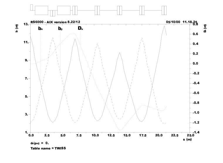 |
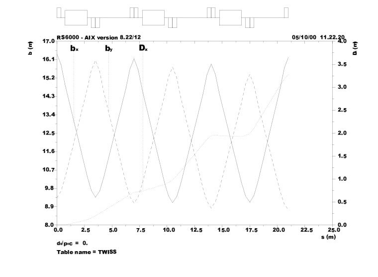 |
The spreader magnet apertures are minimised when
the lowestenergy channels are split off as soon as the minimum spatial
separation requirement is met. The length of the entire spreader can be
minimised if deflections are sequenced and if the spreader dipoles are
embedded optimally in a FODO structure. Sequencing the deflections implies
that once a channel is fully separated, another spreader dipole is inserted
into the remaining combined channel to increase existing separation kicks.
If the spreader dipoles are properly embedded into a FODO structure, the
natural peak excursion locations of a FODO structure can be utilised to
enhance the channel separation process. To this end the quadrupoles
are centred on the highestenergy centre orbit (10 GeV). After initial
dispersion by a spreader dipole, offmomentum orbits undergo increasingly
larger offaxis bend fields or kicks the lower the momentum when traversing
a defocusing quadrupole. Independent channels are then formed at the peak
of the offmomentum excursion, or just upstream of every horizontallyfocusing
quadrupole. Septum magnets are inserted prior to a channel split to ``straighten''
the rapidlydiverging extracted beam, making the newlyindependent
channel parallel to the next highest energy channel and
keeping the relative separation between consecutive
channels constant. Optimised beam spreader optics for the 4GeV and
10GeV channels are presented in Figures 2. Complete separation of
all energy channels is achieved in under 20 m without interrupting the
FODO optics of the linac. A list of magnet fields and apertures is given
in Table 2 and are based on actual magnet designs. The dipole components
in the spreader quadrupoles can be reduced by averaging or smoothing over
several quadrupoles since the bends are alternating reverse bend/bend.
However, this would required a detailed ray tracing through a physical
layout of the spreader magnets. The total bend of the spreader for all
channels is 0.294 radians, thus reducing the total bend required in each
arc by 0.588 radians.
Table 6.1.2 Beam spreader and arc magnets: General parameters
| Magnet | Number | Length
(m) |
Dipole field
(T) |
Quad gradient (T/m) | Horiz. aperture (cm) | Vert. aperture (cm) |
| Spreaders | 4 | - | - | - | - | - |
| Spreader dipoles | 4x3 | 2 | 1.5-1.9 | - | 60 | 10 |
| Spreader septa | 4x3 | 2 | -1 | - | 40 | 10 |
| Spreader quads | 4x16 | 0.75 | 0-4 | 7.7 | 25-60 | 10 |
| Individual arcs | 7 | - | - | - | - | - |
| Arc comb. funct | 7x17 | 1.5 | - | 4.3 | 30 | 10 |
| Matching quads | 7x2 | 1.5 | - | 4.3 | 30 | 10 |
6.1.4 The Arcs
To design a machine without an active (pulsed)
section to match the different arc channels to the linac optics requires
that a suitable periodic structure be imposed throughout the machine. Short
FODO cells have a large energy acceptance and small transverse beam sizes.
The structure of the rf cells described in section 1.2 is continued through
the spreader. In the arcs the same cell and focal length; i.e. phase advance,
is preserved, but longer, combined function magnets are used instead. This
has the effect of not only reducing significantly the number of magnets
required, but also lowering dispersion and, correspondingly, momentum compaction,
or M56=![]() .
.
Table 6.1.3 Example M56 values for Fs=30o in a 3-11 GeV, 4-turn RLA.
| Momentum (GeV) | 3 | 4 | 5 | 6 | 7 | 8 | 9 | 10 | 11 |
| M56 (m) | inj. | 0.5 | 0.65 | 0.8 | 0.9 | 1.0 | 1.1 | 1.2 | 1.3 (ext.) |
While there is significant flexibility in the RLA bunching scenarios, the RLA arcs must be designed to match the parameters of the bunching scenario in order to obtain the required longitudinal motion. In ref. [5] the scenario has a fixed acceleration phase of 30o with M56 increasing from arc to arc, with the first arc (4 GeV) at M56=0.5 m and the last arc (10 GeV) at 1.2 m (Table 3). The M56 value is determined by the dispersion or amount of dipole bend per arc cell, so, ultimately it determines the number of cells in an arc. Also, the total length of each arc must be ``finetuned'' to match an integral multiple of the rf wavelength which is 1.363664 m at 220 MHz. Not only must the central value of momentum compaction (M56) be specified, but also its derivative with respect to momentum must be zero. Horizontal sextupoles are employed to cancel the first derivative of momentum compaction with vertical ones added to stabilise and balance the off-momentum optics. As a consequence, 90o cells are employed for the lowest energy (4 GeV) primarily because they support strong sextupoles with minimum degradation of transverse dynamic aperture. (Although 90 # has the added advantage that the beam size in both planes is minimised simultaneously, the short cell length is the more significant restraint.) For higherenergy arc channels, the cell phase advance decreases proportionally.
Cancellation of dispersion and the first derivative can be achieved by requiring an integer phase advance across the arc for all channels. If 24 cells are used (including the beam spreader cells), then 4, 6, and 8GeV arcs have automatically approximately an integer phase advance. The 10GeV arc gradients have to be gently tuned to the closest integer; representing only a degree change in the individual cell phase advance. Note that the beam spreader sets up an unavoidable, but periodic, dispersion wave through the arc, but, because of the unbroken periodic structure, beta functions automatically match closely. Similarly, on the opposing side, the 5, 7, and 9GeV arcs use 35 cells, with the 9GeV gradients being adjusted slightly to reach the nearest integer tune. The entire length of the arc with two beam spreaders is 168 m.
As mentioned before, the arcs are nested so that the bend per cell cannot be adjusted to control the central value of M56 independently for each channel. To control the value of M56 in this scheme, the dipole component (which is approximately equal initially in both combinedfunction magnets) is moved from the horizontallyfocusing combined function magnet in the lowest energy channel to the horizontallydefocusing combinedfunction magnet in the highest channel, with the other channels having intermediate distributions. That is, only the horizontallydefocusing magnet in the 10GeV channel has a dipole bend (0.16 radians in 16 magnets). The 4GeV channel had 0.08 radians in 33 arc magnets (17 horizontallyfocusing and 16 horizontally defocusing). The goal is to scale M56, or momentum compaction, proportionally with energy and match the rf bucket. With this technique, momentum compaction varies from 0.012 to 0.07 for the 4 and 10 GeV arc cell unit, respectively. Because this matching technique is linear, using only phase advance, no adverse impact is observed on dynamic aperture. Alternatively, a matching section with varied dipoles can be used for dispersion matching along with additional families of sextupoles to handle the first derivative. The length of such a section and the impact on dynamic aperture would need to be carefully evaluated.
Because this matching technique is linear, using only phase advance, no adverse impact is observed on dynamic aperture. Alternatively, a matching section with varied dipoles can be used for dispersion matching along with additional families of sextupoles to handle the first derivative. The length of such a section and the impact on dynamic aperture would need to be carefully evaluated.
6.2 Second recirculator RLA2
The design of the second RLA is optimised for
the normalised acceptance of 15 cm.rad. Its design is copied from that
of ELFE at CERN [1]
with the
notable exception that the final energy is 50GeV
and the energy gain per turn is 10 GeV instead of 3.5 GeV.
6.2.1 Design Criteria
The problems associated with the spreader are less serious than for the case of RLA1 described in Section 6.1 thanks to the reduction of both the relative energy spread and the beam emittance. This is why the ELFE design could be used with some modifications associated with the larger acceptance of the RLA.
6.2.2 rf cells
The rf cells are of FODO type. It has been examined whether triplet focusing was more attractive [2]. For a constant length of the accelerating LINAC, it is not.
Four LEP type rf cavities are installed between each quadrupole for a total length of 14.5 m. The phase advance of 76.345o , which provide the minimum value of the b-functions can be achieved with quadrupoles of length 0.5m with a pole tip field of 0.5T.
The maximum value of the b-functions is 49.7m. It can be shown easily that the increase of the value of the b-functions with energy, at successive passes, is smaller than the increase of the energy. Consequently the normalised acceptance of these cells is that at injection. The details of this analysis can be found in ref. [3].
6.2.3 The Arcs
As in ELFE, the arcs are made of isochronous cells.
The optics functions associated with these cells is shown in Figure 6.2.1.
The value of the average
dispersion function can be adjusted by specifying
its value at the end of the cell. A complication of the isochronicity problem
is introduced by the existence of the vertical spreader. The latter has
a huge effect on the path length and the matching of the matrix element
M56 over the arc is not easy.
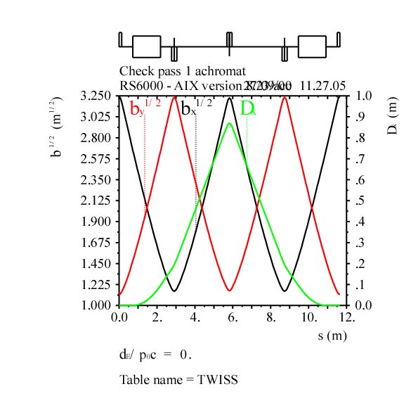
Fig. 6.2.1 Isochronous cell for the arcs
of RLA2.
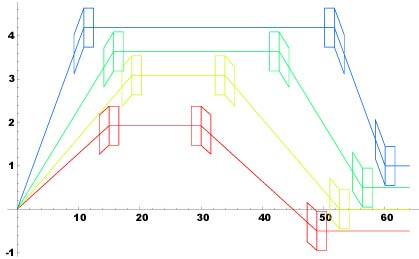
Fig. 6.2.2 Typical beam spreader for RLA2.
6.2.4 Beam Spreader
A passive beam spreader is used to separate the different energy turns of the RLA into independent magnetic channels: 16, 26, 36, and 46GeV channels on one side and 21, 31, and 41 GeV on the opposing side giving a total of 7 separate return arcs. Opposite to the case of RLA1, the separation is vertical as it makes the width of the tunnel the smallest possible. A possible design of this spreader is shown in Figure 6.2.2. A design with four dipoles has been chosen to reduce the vertical dispersion created by this system. Here the problem is to pile-up the separation dipoles so that there is no overlap of their yokes, and to obtain isochronicity as mentioned above. The matching of the rf cells to the arc through this spreader can be done. The optical functions in the matching section are shown in Figure 6.2.3. The separation of 0.5 m between the central orbit of the arcs is assumed to be sufficient to accommodate the magnet yokes. This distance can be increased by modifying the place of the last dipole of the spreader system and rematch the optics accordingly. The limitation to this process is imposed by the increase in aperture associated with the increase of the vertical dispersion. In order to illustrate this, the acceptance of the machine, obtained after the full arc matching, over the four passes is shown in Figure 6.2.4.
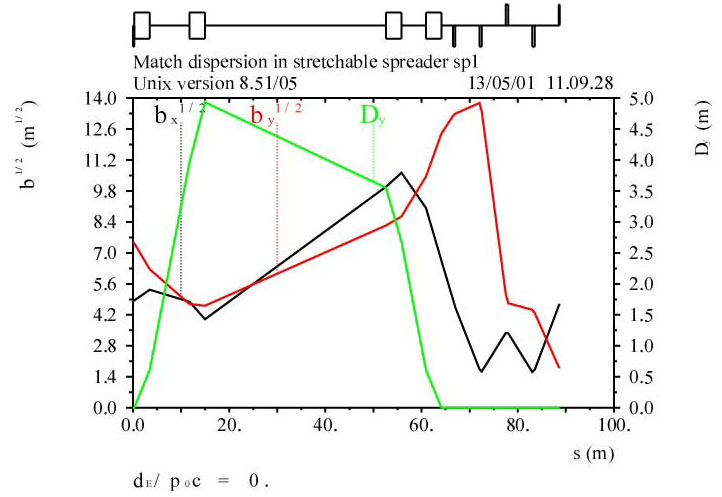
Fig. 6.2.3 Matching section between the
rf cells and the arcs of RLA2.
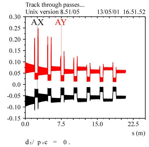
Fig. 6.2.4 Acceptances of the RLA2 during
the four passes. Note that the acceptance
is limited by the vertical dispersion. The opposite
of the horizontal acceptance has
been plotted in order to make a clear separation
from the vertical plot.
6.2.5. Multi-Bunch Beam Loading Compensation in the RLAs
Beam loading in RLA2 can introduce can energy variation between leading and trailing bunches of about ± 0.73% [4] assuming that the cavities are on resonance. The energy shift along the bunch train is larger than the rms beam energy spread in the muon storage ring (0.5%), and it, therefore, needs to be reduced by a compensation scheme. While in the RLA1 muon beam fills the complete circumference, in RLA2 long gaps between bunch trains may complicate the beam loading compensation in some of the schemes proposed [4].
A satisfactory beam loading compensation can be
achieved by a bunch spacing slightly different from an integer multiple
of lrf [5,6].
This compensation scheme was originally suggested
by E. Keil [4].
In Ref. [5] approximative
analytical expressions were derived which
describe the multi-bunch beam loading in such
a scenario. Application to the two RLAs of the CERN neutrino factory shows
that a bunch spacing shifted in frequency by D
f = -14 kHz from the rf frequency frf, combined
with an initial phase offset of about -10o with respect to the
crestof the rf, reduces the bunch-to-bunch energy variation to less than
0.5% peak-to-peak, or to less than a third of the half momentum acceptance
for the muon storage ring [5].
The average accelerating gradient would be 1.66% smaller than the unloaded
maximum value. Similar conclusions were obtained in Ref. [6].
In actual operation, the bunch spacing maystay constant, and the RLA rf frequency will likely be adjusted for varying beam current, assuming that the change required is smaller than typical bandwidths of klystrons and tuning ranges of cavities.
7. Decay Ring
7.1 Generalities
This section describes the design of a 50 GeV muon storage ring that is part of the ongoing study of a neutrino factory in Europe [1]. The Neutrino Oscillations Working Group developed a set of parameters for such a neutrino factory that are desirable from the point of view of neutrino oscillation physics [2]. The upper part of Table 7.1 displays them. The lower part shows the accelerator physics parameters of the muon storage ring designed to achieve the desired physics parameters. Parameters of a 30 GeV muon storage ring were given earlier [3]. A feasibility study of another neutrino factory has been made at Fermilab [4]. Its 50 GeV muon storage ring has somewhat different parameters [5].
Table 7.1: CERN Muon Storage Ring Parameters
| Design momentum | 50 GeV/c |
| Muon fluence | 1014 s-1 |
| Distances to far neutrino detectors | 1000 & 3000 km |
| Vertical slopes | -78.6 & -237.9 mr |
| Normalised divergence at s | 0.1 |
| Configuration | Triangle |
| Normalised emittance at s | 1.667. mm rad |
| Aperture limit | 3s |
| Frequency of rf system | 352.209 MHz |
| Bunch spacing | multiple of 0.851178 m |
| Relative RMS momentum spread | 0.005 |
The muon fluence is the rate at which muons arrive in the muon storage ring. The fraction of muons that decay in the straight section(s) pointing towards distant detector(s) is less than unity, and determined by the geometry of the muon storage ring. In a spherical Earth model with circumference 4 x 10⁷m, the distances to the detectors determine the vertical slopes of the long straight sections pointing at the detectors.With the usual relativistic factor g of the stored muons, the normalised divergence gs' is the ratio of the physical rms divergence s'and the typical opening angle 1/g of the decay neutrinos in the straight section(s) pointing towards distant detector(s).
The normalised emittance is a design goal. Detailed simulations by our colleagues in the US have not yet demonstrated a practical scheme that achieves cooling down to twice our normalised emittance. The aperture limit at three rms beam radii is tight.However, there are many aperture limits in upstream modules, making it unlikely that many muons with larger amplitudes will arrive in the muon storage ring. It is assumed that an rf system is installed, equipped with superconducting LEP cavities. This determines the frequency and the bunch spacing. The rms momentum spread of the muon beam determines the aperture of the storage ring.
7.2 Geometry
In order to achieve a high fraction of muons that
decay in the straight section(s) pointing towards distant detector(s) the
fraction of the circumference occupied by these straight sections should
be large, and the fraction occupied by the arcs joining them should be
small. Sending neutrinos to two detectors at different distances implies
two long straight sections pointing downwards from the surface of the Earth.
Thus, the natural choice is a bow-tie shape, with the two detectors in
opposite directions and the muon storage ring in a (nearly) vertical plane.
The two long straight sections cross at an angle equal to the sum of the
two initial slopes. If this sum is small, long straight sections and compact
arcs fit together well.
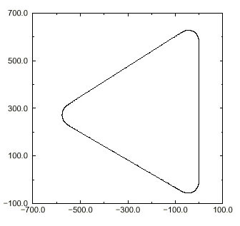
Figure 7.1: Projection of the muon storage ring on a plane tangent to Earth |
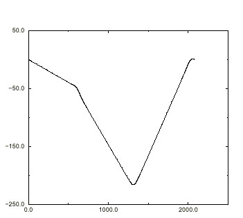
Figure 7.2: Vertical position y along the circumference of the muon storage ring |
Keeping the muon storage ring in a nearly horizontal plane implies that the di-rections towards the two detectors are at approximately right angles. In this case, a triangular shape with two long straight sections pointing downwards towards the detectors, and a third long straight section pointing upwards to close the ring, is more attractive than a bow-tie shape. This is so because with the triangular shape one can still have long straight sections and compact arcs, while with the bow-tie shape with long straight sections crossing at a large angle implies long arcs.
In order to be specific, it is assumed that the
muon storage ring has the shape of an equilateral triangle with rounded
corners. It is easy enough to adapt the exact shape later, once the geographical
positions of the muon storage ring and the two detectors are known. A triangular
shape has been proposed [6]. Fig. 7.1 shows the projection of the
muon storage ring on a plane tangent to Earth. The reader can verify that
the projection is not an equilateral triangle. Fig.7. 2 shows the
vertical position y along the circumference
of the muon storage ring. The origin of y is
arbitrary. The total height of the muon storage ring, less than 250 m,
is smaller than the thickness of the molasse near the CERN site, and one
of the factors influencing the length of the long straight sections.
Fig. 7.3 shows the pitch angle f, and Fig. 7.4
the roll angle y along the circumference of
the muon storage ring. These angles correspond to MAD definitions [7].
The pitch angles in the first two straight sections are f1=
-78.6
mr
and f2 =
-237.9
mr,
respectively, by design. The pitch angle in the third straight section
f3=
+319:6
mr is
the result of a calculation. The roll angle y
does not vanish in the straight sections. Both pitch and roll angle vary
rapidly in the arcs. Table 7.2 shows the ranges of vertical level of the
three arcs. They are of the order of twenty metres.
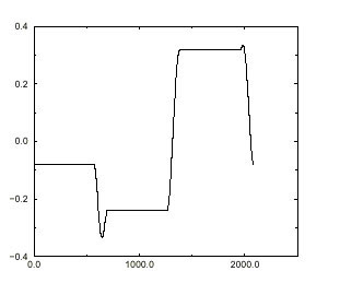
Figure 7.3: Pitch angle falong the circumference of the muon storage ring |
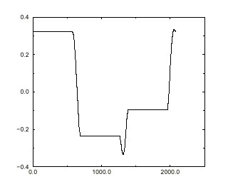
Figure 7.4: Roll angle y along the circumference of the muon storage ring |
Table 7.2: Range of vertical levels y of the three arcs. The origin of y is arbitrary.
| Arc number | 1 | 2 | 3 |
| Top | - 45.211 | - 202.376 | +0.861 m |
| Bottom | - 73.918 | - 216.180 | - 21.530 m |
7.3 Optical modules
The optical design of the muon storage ring is
very modular, and consists of the following modules that will be discussed
in detail below:
This style of muon ring design was implemented
by Keil [NF26] and was previously used [9] for the design of the racetrack
muon storage ring [3].
7.3.1 FODO Cells in the Arcs
The input parameters for the design of the arc cells are the dipole field, the quadrupole field at the aperture radius, the maximum length of a dipole, the number of dipoles in a half cell, and the free space, i.e. the space in a half cell not occupied by dipoles and quadrupoles. A rather conservative dipole field is used, hoping that quadrupoles with this field can be built economically with a single-layer coil. The quadrupole field at the edge of the aperture is lower than the dipole field, because of the tungsten shielding between the vacuum chamber and the super-conducting coil. The quadrupoles is quite short. The dipoles also are assumed to be relatively short in order to have tight focusing and a small dispersion. A round vacuum chamber is assumed, although an elliptical chamber with a smaller height would also work. An engineering study of the packaging of dipoles and quadrupoles in cryostats, bearing in mind the pitch and roll angles discussed earlier, and a cost estimate are needed before another round of studies of the arc cells. Tables 7.3 an7.d 4 show the geometrical and optical parameters of the arc cells, respectively. Figure 5 shows their optical functions.
Table 7.3: Geometrical Parameters Table 7.4: Optical Parameters
| Dipole field | 6 T | Phase advance/2p | 0.25 | |
| Quadrupole field | 3 T | Arc tune | 7.5 | |
| Maximum dipole length | 3 m | Maximum b-function | 16.56 m | |
| Number of arc periods | 30 | Maximum dispersion | 1.375 m | |
| Arc period length | 9.703 m | Un-normalised emittance | 3.52 mm | |
| Dipoles per half cell | 1 | RMS beam radius | 10.28 mm | |
| Dipole length | 2.911 m | Vacuum chamber radius | 30.83 mm | |
| Bending angle | 209.4 mr | Max half momentum spread | 0.0224 | |
| Bending radius | 27.797 m | Focal length of quadrupoles | 3.431 m | |
| Average radius | 46.328 m | Quadrupole length | 0.5 m | |
| Sagitta in dipoles | 0.038 m | Free space in half period | 1.441 m |
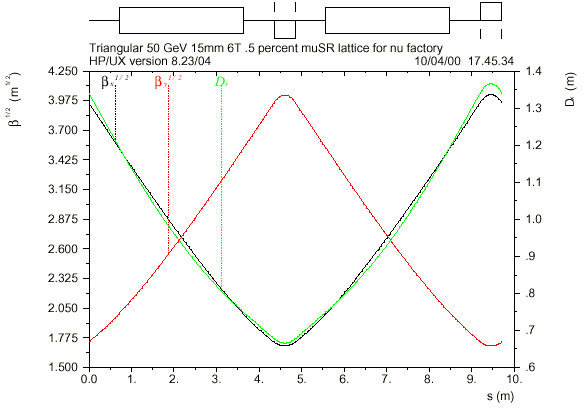 |
7.3.2 Dispersion Suppressors
In order to reduce the dispersion and its derivative to zero in the long straight section, one arc cell at either end of the arcs is replaced by two dispersion suppressor cells each with modified bending, but the same focusing and period length. In thin-element approximation, neglecting the edge focusing in the dipoles, the average bending in the dispersion suppressor cell is one half of that in an arc cell, while the distribution between the two dispersion suppressor cells depends on the phase advance [10]. For finite-length elements, neither is true, and MAD does the matching. The data are adjusted such that the total bending angle is 2p, although all the bending angles change. The length of the dipoles in the dispersion suppressors has not been reduced, although their field is only about half that of the arc dipoles.
7.3.3 Long Straight Section Cells
The input parameters for the design of the long straight sections are the total and the period length, the quadrupole field at the aperture radius, and the normalised divergence. The total length of the straight section has to be a multiple of the period length there. Long periods have the advantage that the lever arm for injection is long, and that the number of components in the long straight sections is small. Normalised divergence and period length yield the phase advance, the b-functions, and the focal length of the quadrupoles. These quantities, together with the emittance, yield the rms beam radius, aperture radius and length of quadrupoles. Since the quadrupole field is low, permanent-magnet quadrupoles look very attractive [11]. There need not be any power nor interlock circuits. Water cooling would only be needed for the power in the charged muon decay products. Table 7.5 shows the parameters and Figure 7.6 the b-functions of the long straight section cells. Figore 7.7 shows the normalised divergence gs' in the whole long straight section, including the adjacent matching cells. It demonstrates that gs' has the design value in the long straight section cells proper, but larger values in the matching cells at either end. Local minima of gs'occur in all quadrupoles. The plot shows them in those quadrupoles that are split into two halves, but not in the others.
The third long straight section is used for fine
adjustments of the tunes. Their fractional parts are the same as in the
LHC. The geometrical layout is identical to that in the other two long
straight sections, but the phase advance and quadrupole gradients in the
cells are changed.
7.3.4 Matching Cells
The matching cells match the aand bfunctions between the dispersion suppressors and the long straight section cells. Four variable quadrupoles, labelled Q1M to Q4M, with three fixed drift spaces between them are used to satisfy these four conditions. At the beginning, their lengths were all arbitrarily set to 1 m. Tracking with COSY-INFINITY [12] for the FNAL design showed a reduction in the dynamic aperture, caused by the fringe fields of quadrupoles in their matching insertion [13], consequently the lengths of the six quadrupoles Q3M and Q3MT were doubled. Tracking with COSY-INFINITY then showed that the dynamic aperture remains larger than the physical aperture [14]. Figure 7.8 shows the b-functions through the matching cells. They vary smoothly between the low values in the dispersion suppressors and the high values in the long straight section. The matching cells surrounding the long straight section for fine adjustments of the tunes have the same geometrical layout, but the gradients of the quadrupoles Q1MT to Q4MT are different from those of Q1M to Q4M.
Table 7.5: Long Straight Section Parameters
| Length of cells | 125 m |
| Quadrupole field | 0.5 T |
| Phase advance in cells | 0-1201 |
| Maximum b-function | 249.7 m |
| Minimum b-function | 115.3 m |
| Maximum RMS beam radius | 29.7 mm |
| Aperture radius | 89.0 mm |
| Focal length of quadrupoles | 84.8 m |
| Length of quadrupoles | 0.35 m |
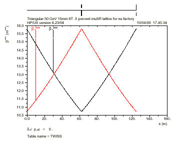
Figure 7.6: Optical Functions of Long Straight Section Cells. Note the suppressed zero on the ordinate. |
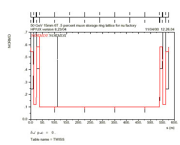
Figure 7.7: Normalised Divergence in the Long Straight Section |
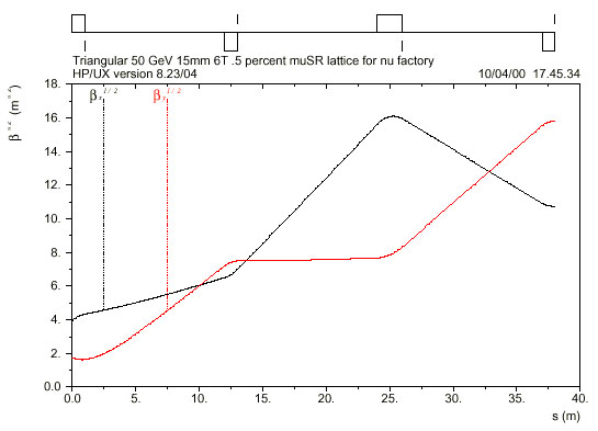
Figure 7.8: Optical Functions of Matching Cells |
7.4 Optics of the Muon Storage Ring
Assembling and matching the complete muon storage ring with finite elements yields the geometrical and optical parameters shown in Table 7.6 and the linear optical functions as shown in Figure 7.9. Tables 7.7 and 7.8 show the parameters of the quadrupoles and dipoles, respectively. Because of the matching with finite elements and edge focusing, the absolute values of the strengths K1 of the QDA and QFA quadrupoles are not the same, and the bending angles in the BD1 and BD2 dipoles are not equal, and not exactly one half of that in the BA dipoles.
Table 7.6: Parameters of the Muon Storage Ring
| Length of arcs | 347.808 m |
| Length of matching sections | 228.000 m |
| Length of straight sections | 1498.950 m |
| Muon decays/detector | 0.2774 |
| Circumference | 2074.831 m |
| Revolution frequency | 144490 Hz |
| Momentum compaction | 0.00257998 |
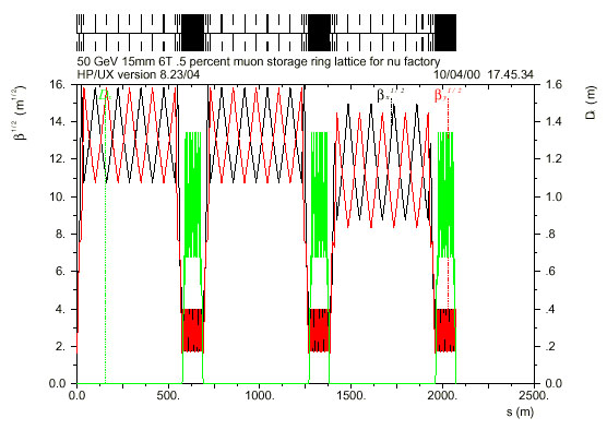
Figure 7.9: Optical Functions of the Muon Storage Ring |
Table 7.7: Quadrupole Parameters
| Name | No. | L/m | K1/m-2 |
| QFA | 33 | 0.500 | +0.603574 |
| QDA | 36 | 0.500 | -0.596693 |
| QFS | 8 | 0.350 | +0.0337579 |
| QDS | 6 | 0.350 | -0.0337579 |
| Q1M | 4 | 1.0 | +0.110848 |
| Q2M | 4 | 1.0 | -0.0809091 |
| Q3M | 4 | 2.0 | +0.0388587 |
| Q4M | 4 | 1.0 | -0.0476056 |
| QFT | 4 | 0.350 | +0.0447628 |
| QDT | 3 | 0.350 | -0.0464925 |
| Q1MT | 2 | 1.0 | +0.135905 |
| Q2MT | 2 | 1.0 | -0.0853225 |
| Q3MT | 2 | 2.0 | +0.0388150 |
| Q4MT | 2 | 1.0 | -0.0486465 |
Table 7.8: Dipole Parameters Table 7.9: Sextupole Parameters
| Name | No. | L/m | F/r | Name | No. | L/m | K2/m-3 | |
| BA | 48 | 2.911 | 0.10469 | SDA | 24 | 0.24 | -5.040708 | |
| BD1 | 12 | 2.911 | 0.052327 | SFA | 24 | 0.24 | +2.830460 | |
| BD2 | 12 | 2.911 | 0.05254 |
7.4.1 Chromatic Effects
Correcting the chromaticity with only two families
of sextupoles in the arc cells achieves the chromaticities shown in Figure
7.10. The tune spread over three rms energy spreads is pretty small. Table
7.9 shows the sextupole parameters. Figure 7.11 shows that the chromatic
functionsb-1db/dd
and
dD/dd
are
pretty bad. Their extreme values are much larger than in the arcs and the
long straight sections alone. They are driven by the matching cells, and
do not change much when the sextupoles are excited.
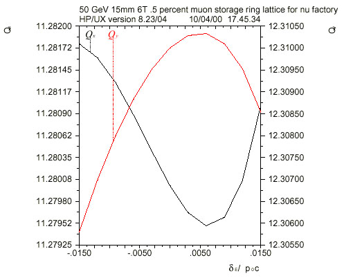
Figure 7.10: Variation of the horizontal tune Qx and of the vertical tune Qy over a momentum spread corresponding to ±3se |
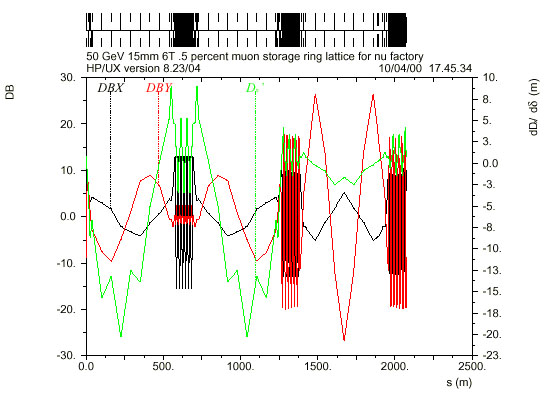
Figure 7.11: Chromatic functions DBX = bx-1dbx/dd, DBY = by-1dby/dd and D'x=dD/dd of the muon storage ring. The sextupoles are not excited. |
4.2 Tracking Results
MAD [7] is used for tracking in two fashions.
First, ten particles are tracked with initial offsets in x
and
y
simultaneously
that correspond to 0.1, 0.2, ...,1.0 times the physical aperture, and vanishing
momentum error d=
0 for 1000 turns, well beyond
the muon lifetime. Rectangular collimators at all quadrupoles have half
apertures equal to three standard deviations of the local beam radius.
Rectangular collimators are unphysical, but they avoid confusion that could
arise by losing large-amplitude particles on a collimator early in the
beam line. Figs. 7.12 and 7.13 show the results. Using the TRANSPORT and
LIE4 tracking methods, and changing the MAD fringe field definition of
the dipoles does not have much effect on the tracking results. Particle
no. 10 is lost horizontally. Particle no. 9 is lost vertically.
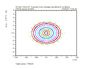
Figure 12: Horizontal tracking results. The physical aperture is ±89 mm at the place where the phase plots are drawn. |
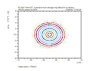
Figure 13: Vertical tracking results. The physical aperture is ±60.5 mm at the place where the phase plots are drawn. |
In the second tracking style, typically 30000
particles are launched with random initial conditions, selected from truncated
Gaussian distributions with standard deviations related to emittances,
momentum spreads, etc. Typically 100 turns are tracked, comparable to the
muon lifetime, and various phase space projections of the final distributions
as well as the distribution of particle losses along the storage ring are
observed [15].
Fig. 7.14 shows the horizontal distribution of
the 28991 muons surviving after 100 turns at the horizontally focusing
quadrupole at the entrance of the long straight section. Fig. 7.15 shows
the distribution of the 1009 muons lost along the circumference of the
storage ring as a function of the turn. Most of the losses occur during
the first few turns in the first long straight section. Losses continue
to occur during later turns in the arcs. Results obtained with both
COSY INFINITY and MAD [14] also include tracking with momentum errors and
are in good agreement with these results.
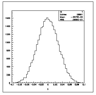
Figure 7.14: Horizontal distribution of the 28991 muons surviving after 100 turns at the horizontally focusing quadrupole at the entrance of the long straight section.The horizontal aperture is ± 0.089 m. |

Figure 7.15: Distribution of the muon losses along the circumference of the storage ring on the right axis as a function of the turn on the left axis |
7.5 Injection
The muon beam is injected into a half period of the long straight section between two quadrupoles. The upstream quadrupole is defocusing and the downstream one is focusing in the plane of injection. Since the muon source is most likely close to the surface of the Earth, the most logical place for the injection system is the upstream end of the first long straight section, pointing downwards. The first element of the injection system proper is a septum magnet just upstream of the defocusing quadrupole. At that quadrupole, the injected beam and the circulating beam, both with radius 3s, just touch. The aperture of this quadrupole must be large enough to take both the injected and the circulating beam. A full-aperture injection kicker just upstream of the focusing quadrupole brings the injected beam onto the design orbit. The kicker field drops to zero before the injected bunch train arrives at the kicker during its second turn. This fall time of the kicker magnet determines the number of kicker modules; the shorter the fall time the higher is the number of modules. Since the finite lengths of the quadrupoles and injection kicker are neglected, its parameters, shown in Table 7.10, are optimistic. Longer periods and higher phase advances in the long straight sections make the injection kicker easier.
Table 7.10: Injection Kicker Parameters
| Maximum kicker voltage | 60 kV |
| Characteristic kicker impedance | 5 W |
| Kicker fall time | 1.0 ms |
| Width of kicker aperture | 177.9 mm |
| Height of kicker aperture | 120.9 mm |
| Deflection angle | 1.934 mr |
| Integrated kicker field | 0.323 Tm |
| Length of kicker modules | 2.703 m |
| Number of kicker modules | 2 |
| Actual kicker voltage | 57.4 kV |
| Magnetic kicker field | 0.0597 T |
7.6 rf system
An rf system is needed in the storage ring for two reasons, (i) to avoid the depolarization due to the different rate of spin precession of the muons in the beam with an RMS energy spread se[16], if the muons are polarized at injection, and (ii) to avoid debunching of the muon beam which would make it unobservable with typical beam position monitors. Table 7.11 shows the parameters of the rf system. I assume that super-conducting LEP cavities are used. This determines the frequency. With a peak voltage of about 100 MV the bucket height is about 3se. The bunch length ss and the bunch area A are those of bunches that would be matched to the rf bucket. Length and area of the bunches arriving in the storage ring depend on the injectors [3]. In the MAD data the rf system was installed at the downstream end of the long tuning straight section, close to the surface of the Earth. The beam port radius of the cavities [17] is well matched to the aperture in the long tuning straight section. Figs. 7.16 and 7.17 show the distributions along the beam axis of a train of three bunches, initially 1.7 m apart, corresponding to a frequency of about 176 MHz, without and with the rf system after 20 turns. Without the rf system, the beam is nearly debunched.
Table 7.11: Parameters of the rf system
| Frequency, frf | 352 MHz |
| Peak voltage, Vrf | 100 MV |
| Harmonic number, hrf | 2438 |
| Bucket height | 0.0145 |
| Synchrotron tune | 0.044885 |
| RMS bunch length | 95 mm |
| Bunch area A = 4psessE/c | 1 eVs |
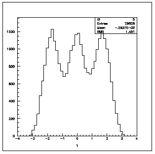
Figure 7.16: Distribution of three bunches along the beam axis without rf system after 20 turns. The abscissa is in metres. |
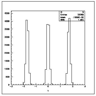
Figure 7.17: Distribution of three bunches along the beam axis with rf system after 20 turns. The abscissa is in metres. |
Table 7.12: Fractional tunes, chromaticities and anharmonicities
| Mode 1 | Mode 2 | Mode 3 | |||
| Q1 | 11.280000 | Q2 | 12.310000 | Q3 | 0.044855 |
| Q'1 | 0.000000 | Q'2 | 0.000009 | ||
| Q''1 | -7.351623 | Q''2 | -38.434398 | ||
| dQ1/dE1 | 20.8132 | ||||
| dQ1/dE2 | -90.0345 | dQ2/dE2 | 42.9659 | ||
| dQ1/dE3 | -0.09741678 | dQ2/dE3 | -0.496526 | dQ3/dE3 | -0.00207224 |
Table 7.12 shows the chromaticities to higher order and the anharmonicities, as calculated by MAD with the fringe fields in the dipoles obtained by putting FINT=0.5 and using the vacuum chamber radius in Table 7.4 as half gap height, and no fringe fields in the quadrupoles. They do not look particularly alarming. Zimmermann has demonstrated [14] that fringe fields significantly change the chromaticities and anharmonicities.
7.7 Conclusions
The design of a muon storage ring for a neutrino factory at CERN meets the requirements of neutrino oscillation physics. The machine fits into the molasse layer in the neighbourhood of CERN, provided that there are few small scale perturbations. The modular optical design achieves a dynamic aperture larger than the physical one. The next step should be engineering studies of the components for the arcs. They should take into account that the arcs will be installed with significant and rapidly varying pitch and roll angles. A procedure is in place that allows the design to be adapted easily to changes in the engineering parameters.
References (to be reordered and completed during final mis-au-point.
Additional reference for section 3
Cappi01 R.Cappi (ed.),
K, Cornelis, J.P. Delahaye, R. Garoby, H.Haseroth, K. Hubner, T. Linnecar,
S. Myers., K.H. Schindl, C. Wyss, Increasing the Proton Intensity of
PS and SPS, CERN/PS 2001-041 (A3); CERN/SL-2001-032 (2001)
References Section 4
[Autin01] B. Autin et al. Conducting Target, to
be published in the proceedings of NuFACT01, Nucl. Instr. and Meth. A
[Ball99] A Ball, A Blondel, S Gilardoni and N
Vassilopoulos, Preliminary Magnetic Horn Studies in the Collection Scheme
for a Neutrino, Factory (Proc. NuFact'99, Lyon, July 1999), NuFact Note
4
[Bauer96] G. S. Bauer et al., The European Spallation
Source Study, vol III, The ESS Council, ESS-96-53-M, ISBN 090 237 659,
1996
[CNGS98] The Cern Neutrino Beam To Gran Sasso,
CERN 98-02, INFN/AE-98/05
[EURISOL] http://www.ganil.fr/eurisol/index.html
[Fabich00] Experimental Observation of MHD Effects
and Proton-Induced Shocks. To be published in the proceedings of NuFACT01,
Nucl. Instr. and Meth. A
[Jackson75] J. D. Jackson, Classical Electrodynamics,
Second Edition p. 588 ed. J.Wiley &Sons New York 1975
[Kirk00] H. Kirk et al.:"TARGET STUDIES WITH
BNL E951 AT THE AGS" PAC01
[Lettry97a] J. Lettry et al., Nucl. Inst. and
Meth. in Phys Res. B 126 (1997)170.
[Lettry97b] J. Lettry et al., Nucl. Instr. and
Meth. B 126 (1997) 130.
[Mansur01] L. K. Mansur et al., J. Nucl. Materials,
296 (2001) 1
[Maugain80] J.M. Maugain, S. Rangod, F.
Voelker, Study of a Horn with Integrated Target for a Neutrino Factory,
NuFact Note 80
[NIM00] Nucl. Inst. and Meth. in Phys Res. A
451 (2000).
[ISAC] P. Schmoor, private communication.
[Ravn79] H. l. Ravn, Experiments With Intense
Secondary Beams Of Radioactive Ions, Phys. Rept. 54 (1979) 203.
[Ravn97] H. L. Ravn et al., Nucl. Instr. and
Meth. B 126 (1997) 176.
[Ravn98] Phil. Trans.R. Soc. Lond. A 356 (1998)
1955.
[Ravn01] H. L. Ravn, The CERN Target and Horn
Concept for a Neutrino Factory Based on Muon Beams. To be published in
the proceedings of NuFACT01, Nucl. Instr. and Meth. A
[Sievers01] P. Sievers, A stationary target for
the CERN neutrino factory. To be published in the proceedings of NuFACT01,
Nucl. Instr. and Meth. A
[Spaminato00] P. Spaminato, Exploration of solid
carbontarget and high radiation facility for target area. To be published
in the proceedings of NuFACT00, Nucl. Instr. and Meth. A
[Weggel99] R.J. Weggel et al. Pion yield vs.
geometry of target and ~20 T pulse solenoid for a muon collider experiment.
PAC 1999, p. 3047-3049
[VanDerMeer61]S. Van Der Meer, A directive device
for charged particles and its use in an enhanced neutrino beam, CERN 61-7
[Zucchelli01] P. Zucchelli. A novel concept for
a anti electron Neutrino Factory, To be published in Phys. Lett. B.
References section 6.1
[1] C. Johnstone and D. Neuffer, A 3-11GeV recirculating
linac for muon acceleration. To be published in NIM.
[2] R.B. Palmer, C. Johnson and E. Keil, A costeffective
design for a neutrino factory. CERN SL/99070 AP also Neutrino Factory
note 9, (Nov. 1999).
[3] D. Neuffer, Fermilab Note, MuCool-75 (2000).
[4] E. Chiaveri, private communication, march
2001.
[5] The Muon Collaboration, Muon Collider: A
Feasibility Study, BNL-52503, Fermi-Conf. 96/092, LBNL-38946, July, 1996.
References section 6.2
[1] ELFE at CERN, Conceptual Design Report. Editor
H. Burkhardt. CERN 9910 (December 1999).
[2] E. Keil, Triplet focusing in recirculating
muon accelerators. CERNNUFACTNote058 (January 2001).
[3] E. Keil, Focusing in recirculating muon accelerators.
CERNNUFACTNote067 (January 2001).
[4] E. Keil, private communication (2000).
[5] F. Zimmermann, ``BeamLoading Compensation
in the Recirculating Linacs of the CERN Neutrino Factory,'' CERNSL2001006
AP, CERNNUFACT Note 071 (2001).
[6] M. Ferrario, V. Fusco, M. Migliorati, ``Beam
Loading Compensation Schemes for the Muon Recirculating Linacs of the CERN
Neutrino Factory,'' CERNNUFACT Note 076 (2001).
References section 7
[1] Refer to NFWG
[2] A. Blondel et al., Beam and Experiments:
Summary, presented at _-Fact99, Lyon, France, 59 July 1999.
[3] R. Palmer, C. Johnson and E. Keil, A Cost-Effective
Design for a Neutrino Fac-tory, presented at _-Fact99, Lyon, France,
59 July 1999, also CERN-SL/99-070-AP (1999).
[4] http://www.fnal.gov/projects/muon collider/nu/study/report/machine
report/
[5] C.J. Johnstone, http://www.fnal.gov/projects/muon
collider/nu-factory/subsys/ ss-stgring/50gev table.gif
[6] A. Verdier, Geometry of the muon storage
ring, Neutrino Factory Note 13 (Feb2000).
[7] H. Grote and F.C. Iselin, The MAD Program,
Version 8.16, Users Reference Manual, CERN SL/90-13 (AP) Rev.4 (1995).
[8] S. Wolfram, The Mathematica Book,
Third Edition (Cambridge University Press,Cambridge UK 1996).
[9] E. Keil, Muon Storage Rings Design with
Simple Mathematica Packages, CERN-SL-99-053-AP (1999).
[10] E. Keil in: Theoretical Aspects of the
Behaviour of Beams in Accelerators and Storage Rings, M.H. Blewett
ed., CERN 77-13 (1977) 22.
[11] E. Keil, Permanent-Magnet Quadrupoles
for Neutrino Factories, CERN-SL-2000-006 (AP) (2000), also Neutrino
Factory Note 15 (Feb 2000).
[12] K. Makino and M. Berz, COSY INFINITY
Version 8, Nucl. Instrum. Meth. A427(1999) 338.
[13] F. Zimmermann et al., Fringe Fields and
Dynamic Aperture in the FNAL Muon Storage Ring, CERN-SL-2000-011 (AP),
also CERN-NUFACT-NOTE-21 (2000).
[14] F. Zimmermann, Fringe Fields, Dynamic
Aperture and Transverse Depolarisation in the CERN Muon Storage Ring,
CERN-SL-2000-012 (AP), also CERN-NUFACT-NOTE-22 (2000).
[15] E. Keil, Histograms of MAD Tracking Results,
CERN-SL-Note-99-061-AP, also Neutrino Factory Note 12 (1999).
[16] A. Blondel, Muon polarisation in the
neutrino factory, presented at _-Fact99, Lyon, France, 59 July 1999,
also Neutrino Factory Note 7 (1999).
[17] K. Aulenbacher et al., ELFE at CERN
Conceptual Design Report, CERN 99-10 (1999).