CERN Neutrino Factory
Working Group Technical Note
R. Horne, C.D. Johnson
25/11/99
(from previously unpublished material)
Post-irradiation Examination
of a High-Intensity Proton Beam Target
This Technical Note was
distributed at CERN in manuscript form on 10/10/85. It contained several
colour photographs.
There has recently been a renewed
interest in high-intensity and high-power proton targetry for neutrino
production and nuclear spallation sources. We have taken advantage of the
newly available techniques of Web publishing and computer enhancement
of photo images to re-issue the original document in an updated form.
At the time of this study the CERN Proton
Synchrotron, PS, could deliver a beam onto the antiproton target of up
to 5 bunches, spaced by 105 ns, per machine cycle (pulse) with the following
properties:
| Energy |
26 GeV |
| Intensity (maximum) |
2.5 x10¹² p/bunch |
| Repetition rate (max.) |
0.4 Hz |
| Bunch length (4sigmaz) |
25 ns |
| Beam spot size at target of (4sigmar)
|
1.6 mm |
| Energy deposited in target (50 mm) |
1.5 kJ per pulse (5 bunches) |
| Peak energy density in beam: |
50 kJ mm-2 per
pulse |
| Mean power absorbed in target at maximum repetition rate |
600 W |
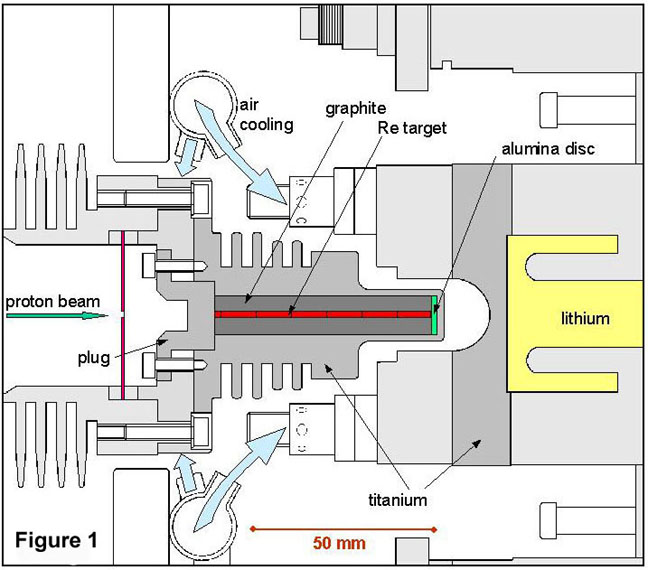
The antiprotons (and other secondary particles - notably
negative pions) produced in the target were collected (focused) by a lithium
lens placed very close to the target as illustrated in Figure 1: Target + Li Lens. The
high-density target was a 3 mm diameter x 50 mm length rod of rhenium (later
iridium was used) pressed into a graphite cylinder, itself a press fit
inside a finned titanium container that was bolted on to a finned aluminium
heat sink with a black anodised finish (seen to the left of the target
assembly in Figure 1). The whole assembly - target plus heat sink
was air cooled. Some photographs of the target and target/lens assembly
installed in the antiproton production zone are shown below.
Click on the photos to see enlarged images
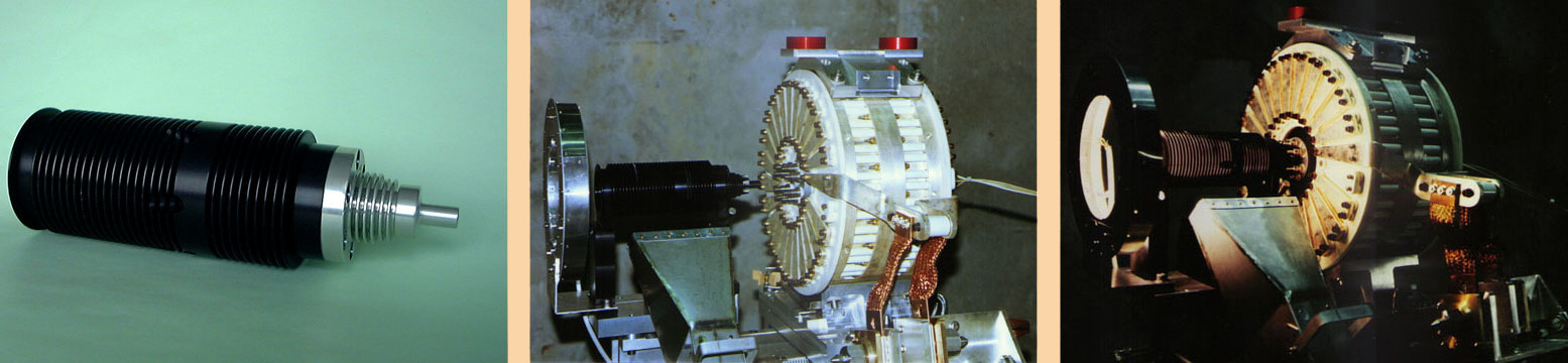
a) A target assembly, b) a similar target mounted
upstream of the lithium lens, c) the target/lens installed in the beamline
with illumination for TV monitoring
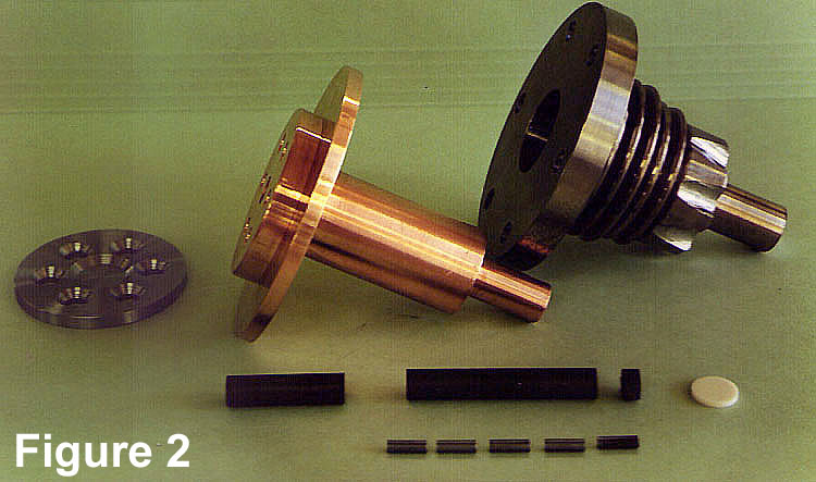
The component pieces of a typical target before assembly
are shown in Figure
2. In this version a copper heat sink was installed between the graphite
and the titanium container. The rhenium core was made up from pieces 3
mm diameter and 10 mm long. The alumina disk at the downstream end of the
rhenium core was introduced to improve the fatigue lifetime of the downstream
exit window of the titanium container. Previously two steel containers
had ruptured on axis at the exit window after 105
beam pulses. This was attributed to fatigue failure.
The target chosen for post-irradiation dissection had
the simpler form shown in Figure 1.
By removing the upstream plug and then cutting through the target snout
immediately in front of the alumina disc, the target and its surrounding
graphite cylinder could be pressed out from the titanium container The
graphite cylinder was then sheared longitudinally with a special tool exposing
the rhenium rods for visual inspection. The target had been irradiated
for six days and, taking account of beam intensity fluctuations and duty
cycle, the estimated total proton flux was between 1 and 1.5 1017
protons. Previous experience with tungsten and rhenium targets had led
us to expect that the rods would be shattered by beam-induced thermal shock
soon after the start of irradiation at full intensity. Our target was designed
to contain the fragments within the graphite sheath. The time evolution
of normalised yield of secondary particles (antiprotons, electrons, negative
pions) measured seperately after startup, indicated that breakup reduced
the effective target density by less than 10%. Earlier results from long-term
irradiation of copper targets in graphite had indicated a more important
loss of up to 30% in effective density due to fracture and void formation.
Our purpose in carrying out this post-irradiation target
inspection was to study the fracture pattern and to confirm our calculation
that most of the damage would occur in the downstream end of the rhenium
rod where the heat load was greatest, see Figure
3.
In the following set of four pictures, Photos 1 and 2
show the target before dissection. The target snout was subsequently sliced
through at the interface between the graphite and the alumina disc and
a further slice of 10 mm length was cut off the end of the snout. Photo 3
is a view of this slice from the downstream end exposing the rhenium core,
the graphite plug and the outer sleeve of titanium. Photo 4 shows
the upstream face of the alumina disc - it exhibits radial cracks. Click
for an enlarged view.
|
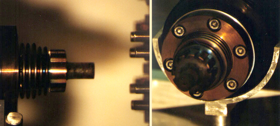
Photo 1 Photo2
|
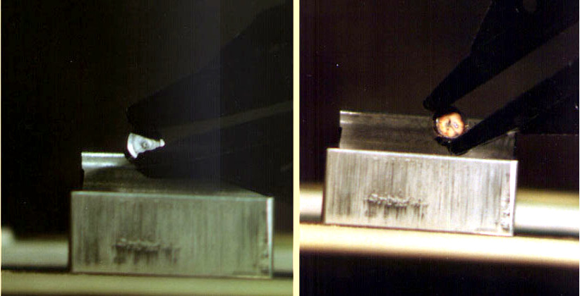
Photo 3 Photo4
|
The graphite slug containing the
10 mm downstream end of the target was then pushed out from the titanium
sleeve and split. The rhenium was in fragments and these are shown in Photo
5.
The remaining upstream 40 mm length
of rhenium was still inside the main body of the target (Photo 6). It was
pressed out and the surrounding graphite cylinder was split over its entire
length. The results are shown in Photos 7 and 8. The greatly enlarged views
(click on the photo) show that the rhenium in the upstream 30 mm has
broken into many short lengths and that the region from 30 mm to 40 mm
had disintegrated in a similar way to the 10 mm end section (Photo
5). This qualitatively confirms the prediction (Figure
3) that the maximum thermal shock is expected in the downstream 40%
of the target.
|
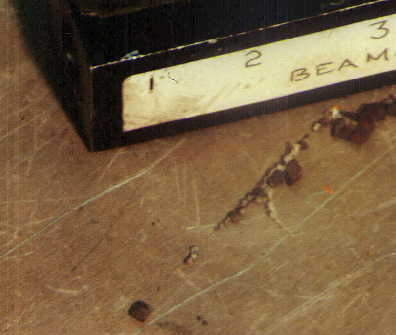
Photo 5
|
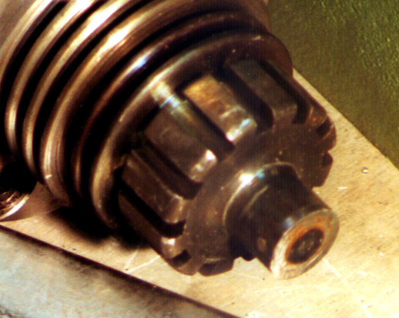
Photo 6
|
|
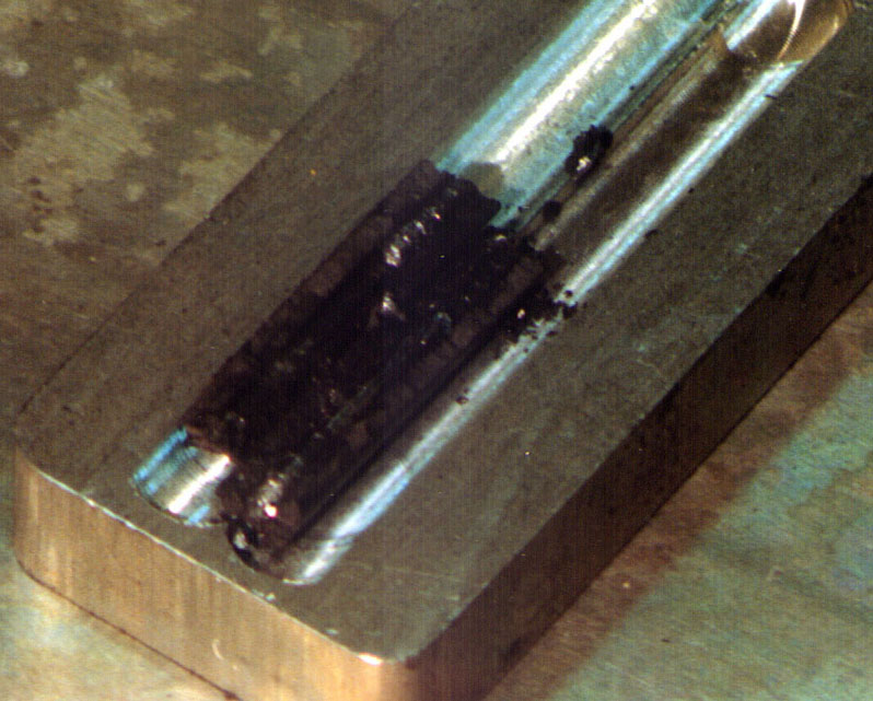
Photo 7
|
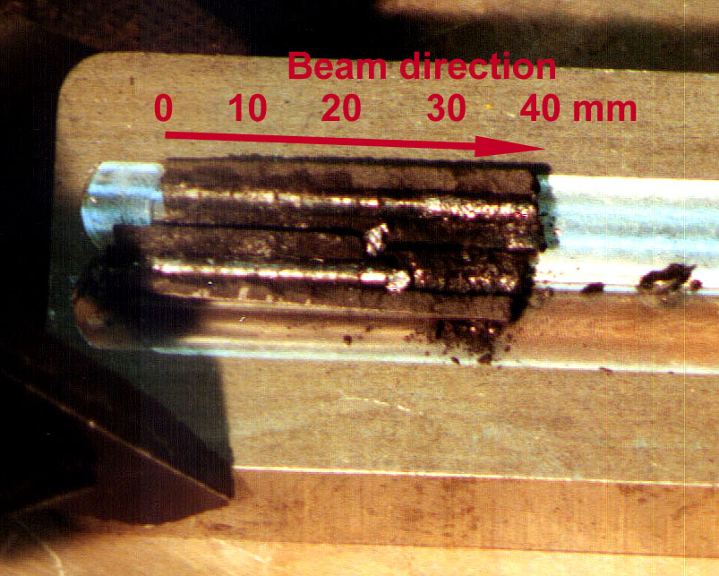
Photo 8
|
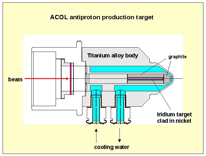
Summary These
photographs confirmed our understanding that within the antiproton targets
the high-density target material (rhenium or iridium) was shattered by
beam-induced thermal shock, but that the fragments could be contained to
provide a target with an effective density better than 90% of the solid
material. A subsequent improvement in target design - intended for higher
intensity proton beams - was water cooled and in some assemblies the 3mm
diameter iridium core material was plated to a diameter of 6 mm with
nickel to improve the containment of the fragments. A target of this design
is shown below. Its lifetime was in excess of 107
beam pulses with no significant depletion of effective density.
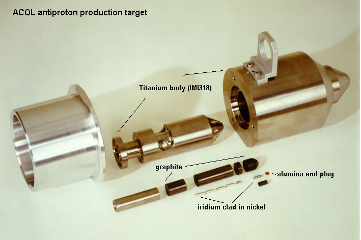
Schematic sectional drawing and component
parts of the Antiproton Collector (ACOL) target.
This technical note was originally
written in manuscript form, dated 10/10/85.
cdj@mail.cern.ch