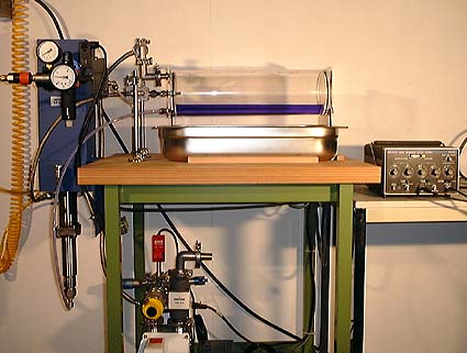
Photo 1 Pump (upper left) and jet chamber
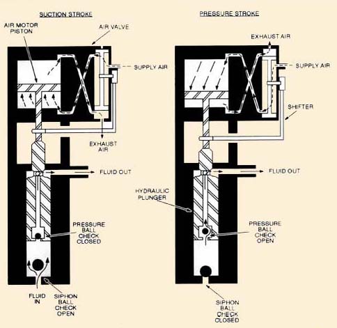
Nordson piston pump schematic
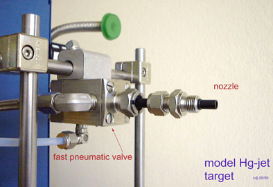
Photo 2 Close-up of needle valve and jet nozzle
NF Note 27
Study of the Behaviour of a Pulsed Liquid Jet Target
C. D. Johnson, CERN, 30th May 2000
This Web document describes laboratory tests of a water jet using a
Nordson piston pump (Model 25B 16:1, Nordson Corp. Ohio, USA) and 5 mm
diameter Nordson needle valve (A7A-LBS) - a high-tech water pistol!
These tests are a preliminary stage in the development of a mercury-jet
pion-production target for a neutrino factory based on a muon storage ring
[Refs.1,2]. Click on pictures
for enlarged images
|
Photo 1 Pump (upper left) and jet chamber |
Nordson piston pump schematic |
Photo 2 Close-up of needle valve and jet nozzle |
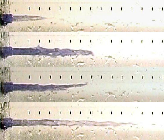
A test of a simple photographic technique was made. The jet chamber
was illuminated by two 1 kW flood lamps. A Sony PC7 digital video
camera with a shutter speed of 1/4000 s was used to photograph the jet
shots asynchronously. Photo 3 is a set of three pictures of the jet
emerging from the nozzle. In each case field 1 of a single frame
is captured and displayed. From comparison between the two fields
in a single frame (see Photo 4) the jet velocity can be measured. In photographs
3 and 4 this was 8 m/s.
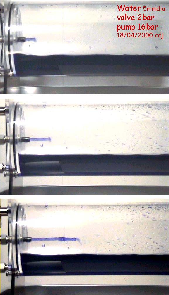
Photo 3 Three shots chosen to illustrate different stages of the jet formation |
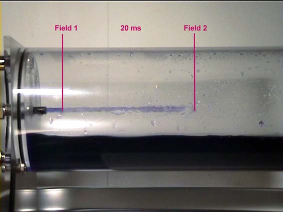
Photo 4 Fields 1 and 2 of a single frame |
When the jet velocity is increased to 20 m/s, in air at atmospheric
pressure (Photos 5 & 6), an instability develops after about 20 cm.
These two succesive photos (40 ms apart) were taken with a Canon XM-1 DV
camera in frame mode (25 fps), shutter speed 1/8000 s
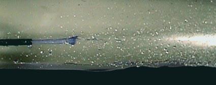
Photo 5 |
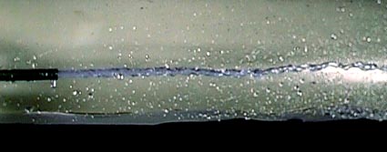
Photo 6 |
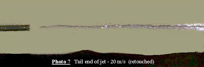
After 50 ms the needle valve closes and the tail end of the jet appears
as in Photo 7. N.B. It is thought that a clean tail cutoff is required to reduce eddy current effects
for a mercury jet in a magnetic field.
 |
Long feed to jet nozzle In practice
a jet target would probably be engineered with a feed from the valve to
nozzle of length 1 m or more. This would facilitate mainenance and
would remove the relatively bulky valve from the confines of the target
region. A 1 m length of translucent polyamid hose was inserted between
the needle valve and the nozzle (OD 8 mm, ID 6 mm). With water as
the test fluid, the surface tension at the nozzle exit retains the water
in this tube prior to firing the jet for the first time. However,
as the valve closes a negative pressure forms due to the velocity of the
water remaining in the tube. This results in a part of the tube fill
being ejected from the nozzle end leaving an air space plus some water
droplets. The latter are ejected in the head the subsequent jet.
This is illustrated in Figure 1. The length of the air pocket was
found to be approximately 5 mm per m/s velocity of the jet. A solution
would be to prime the feed tube before each shot using a small auxiliary
pump. Photos: Canon XM-1 DV, frame mode (25 fps), shutter speed 1/2800
s.
 |
Typical 6 mm dia jets from set-up in Fig 1. Marks are 10 mm intervals |
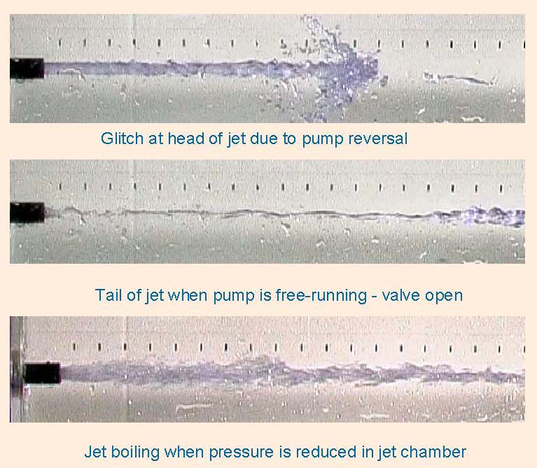
The piston pump used for these tests (Nordsen 25B) has a pressure range
up to 128 bar but a volume per stroke of only 50 ml. Two modes of operation:
valve control of the jet; and valve open, free-running pump, have been
studied. The latter are illustrated below. Splash onto the jet chamber
walls is a problem in this mode. A fix is on the way. The pump is double-stroke
(bi-directional). Between strokes, in the configuration with the valve
fully open, a pressure glitch appears to break up the jet (see photo).
For single-shot work controlled by the valve, starting with the piston
at one end, it can produce one or two jets 5 to 6 mm diameter lasting for
50 ms (50 cm at 10 m/s).
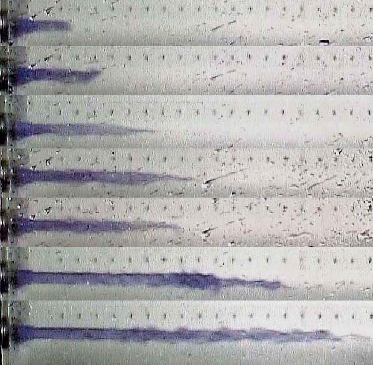
Free running pump water pressure 24 bar - 1 m tube to nozzle |
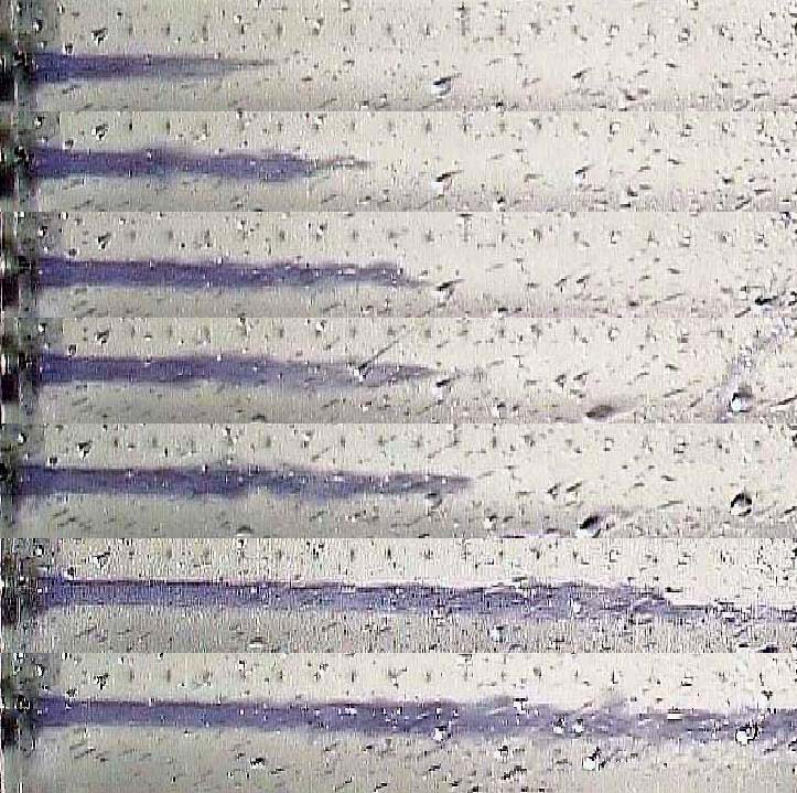
Free running pump water pressure 48 bar- 1 m tube to nozzle |
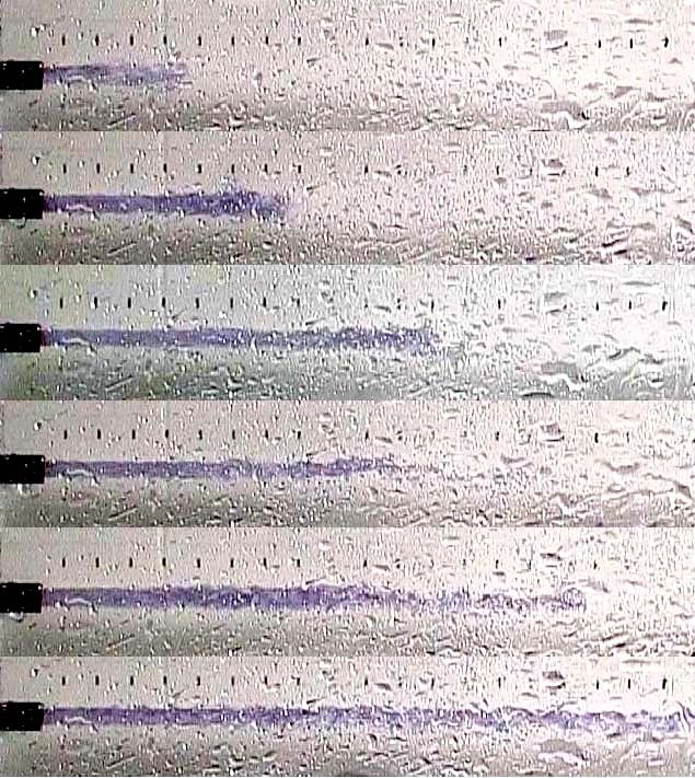
Free running pump water pressure 24 bar - short nozzle |
Some Miscellaneous pictures |
Conclusions Of the two operating modes, the free-running pump with a short nozzle produces the better jets, but the tails are ragged. Valve control of the jet with a short nozzle (photos 3 to 7) can be improved by using a larger needle valve. The long feed-tube option would benefit from the addition of a small priming pump. This is probably the preferred operating mode for tests with mercury. If we decide to stick with the piston pump with valve control of the jet for the next full-scale assembly, then we should use a pump of greater volume (e.g. Nordson 180D).
References
[1] K. McDonald (Ed) A Proposal for an R&D Program for Targetry
and Capture at a Muon-Collider Source, P951, BNL 1998
[2] H. Kirk, Targetry at a Mu+Mu- Collider, THP34, PAC 1999